

Review: How CANbus OCS-I/O Peripherals Work with the Horner Canvas 4 PLC/HMI

External I/O peripherals can be connected to Horner PLCs with HMI—and are often required. Jaroslav Blažek (blaja.cz) tested how an OCS-I/O module with digital and analog inputs/outputs works over the CANbus with a Canvas 4 PLC/HMI.
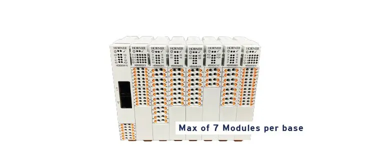
OCS-I/O is a modular system for locally expanding PLC inputs and outputs or for use as remote distributed I/O. A single base unit supports up to 7 I/O modules, and up to 16 base units can operate within one CsCAN network.
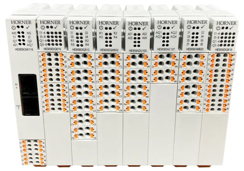
Review by Jaroslav Blažek
Like any peripheral system, Horner uses a communication base (interface) with a CANbus connection via RJ45 connectors. Individual I/O modules are attached to this base, all mounted on a DIN rail. The module dimensions are 19 × 125 × (76) mm.
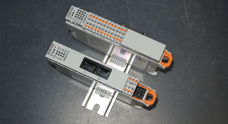
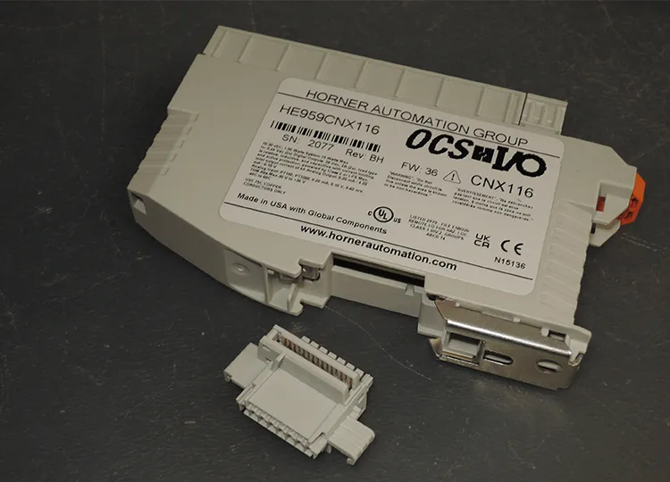
Internal connections between modules are made via a connector located at the bottom of the DIN rail, integrated into each module.
As shown in Horner’s catalog, each base unit can support up to 7 modules, and up to 16 such bases can be connected to a Canvas PLC—which is more than we expected. Another limitation is addressing, as described in the manual, see the Download section of the product page.
That’s how it works—once everything is set up correctly. Now let’s walk through how to do it and whether there are any pitfalls. There are a few—but they’re manageable.
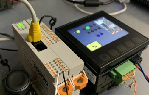
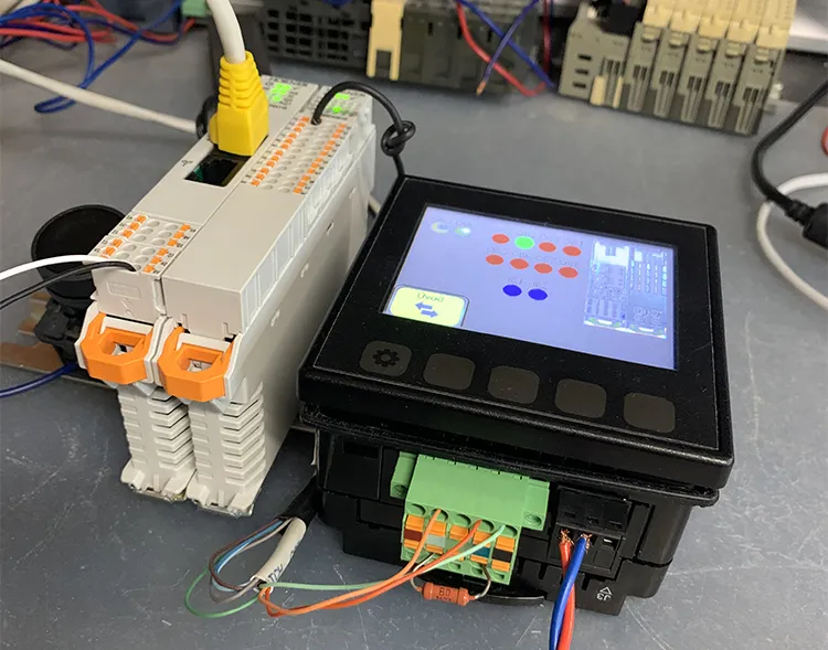
We connect the CANbus line to the PLC via a standard terminal block. The CANbus requires just two wires (CAN_H and CAN_L), plus shielding and a 120-ohm termination resistor. For demonstration purposes, we included the resistor, although for short bench setups it will work even without termination—and even with simple wiring.
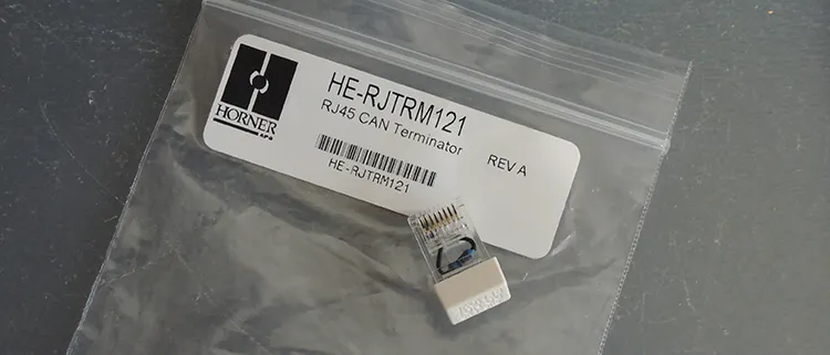
In the application, termination on the last device is implemented using a connector with a built-in resistor.
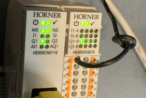
Pay attention to the MS and NS LEDs on the base unit. If they are blinking instead of being steadily lit, something is wrong—either a configuration issue or incomplete parameterization. We’ll show the most common mistake.
First, configure the peripheral in the hardware configuration under the (CsCAN) I/O tab—but before that, make sure to configure the CAN1 port using the Config button.
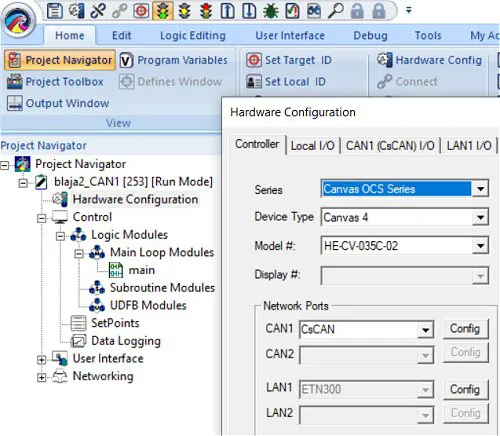
Here’s the key step: reduce the default speed from 1 MB to 125 kB. The lower speed is not immediately obvious in the settings, so be careful—at higher speeds, the peripheral will not function properly.
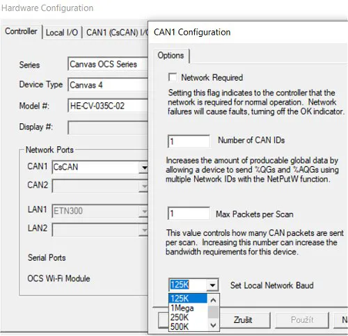
In the (CsCAN) I/O tab, select the connected base unit (HE959CNX116) and activate the Auto Populate All function. This scans the CANbus network, detects the connected base, and reads its UUID (unique identifier).
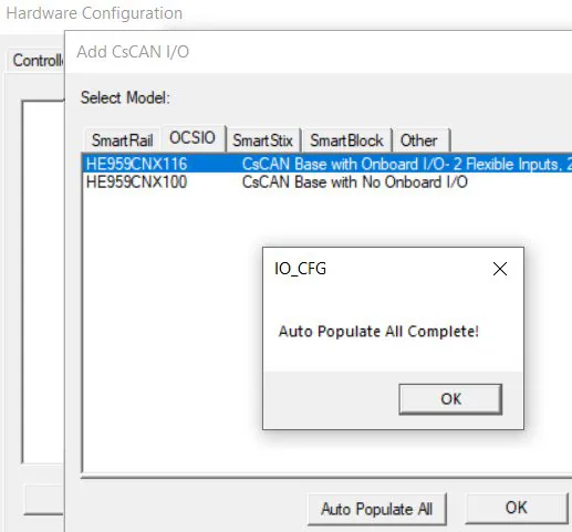
Success is guaranteed—but only at a bus speed of 125 kBd.
Note: When using only one peripheral, this step is not strictly required according to the manual, but it’s a useful way to verify communication.
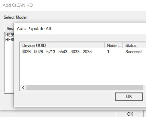
If everything is configured correctly, the result will look like this.
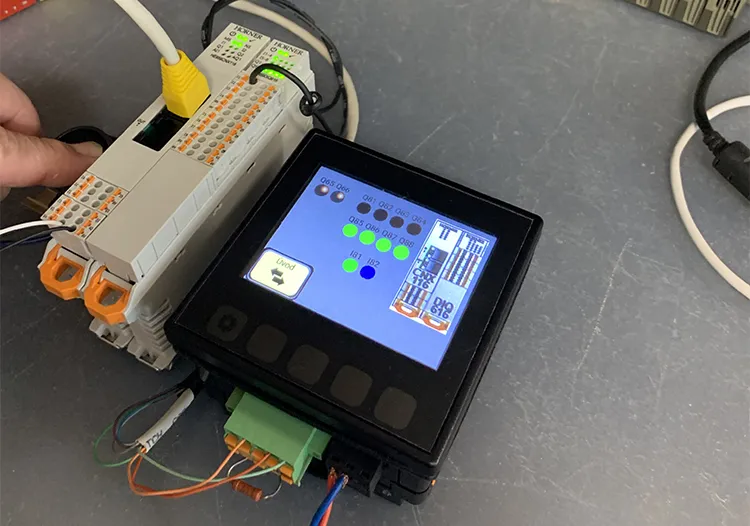
You can also verify the CANbus connection and peripherals directly on the PLC via the system menu.
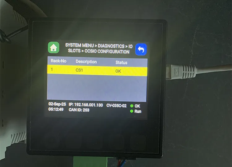
The connected base and DIQ module are displayed, along with the UUID mentioned earlier.
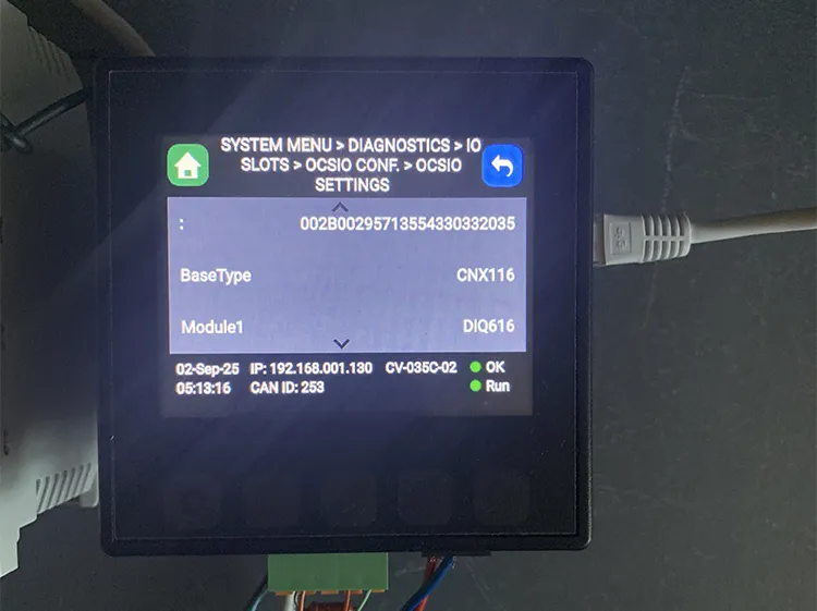
If needed, you can also inspect the CANbus signal using an oscilloscope to confirm activity. The time scale here is 10 microseconds.
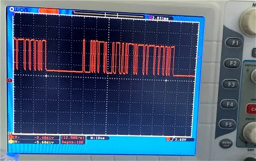
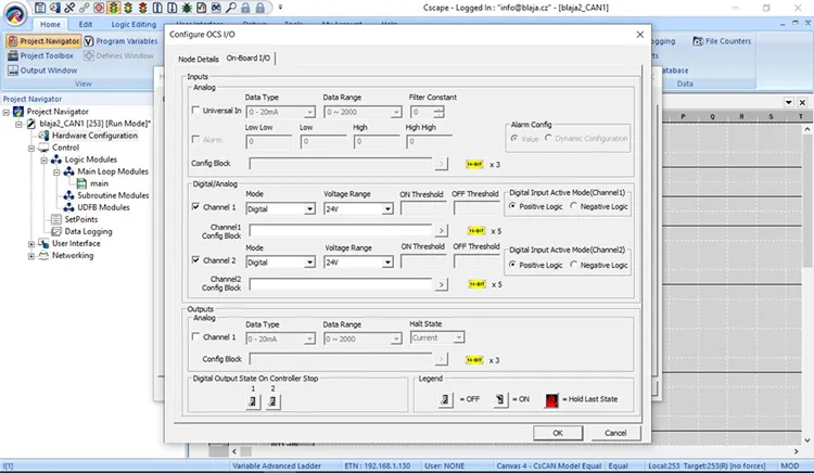
In the configuration, assign addresses and define 15 words for the diagnostic block. These must be addressed, though they don’t have to be actively used. You can also adjust base unit input parameters in the On-Board I/O tab.
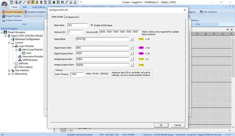
The setup is intuitive—analog and digital signals can be enabled or disabled as needed.
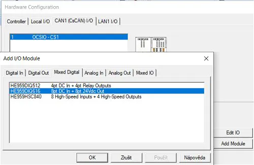
We then added another I/O module: 8 digital inputs and 8 digital outputs.
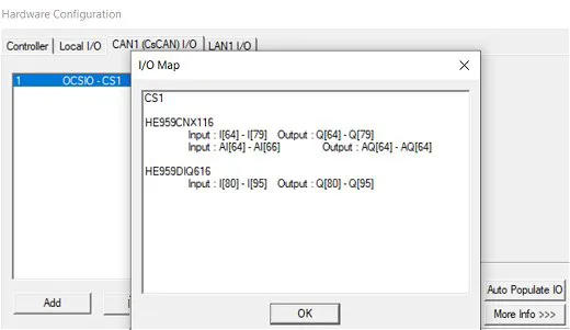
A useful feature: if you’re unsure about addressing (where each module starts), simply click "More Info".
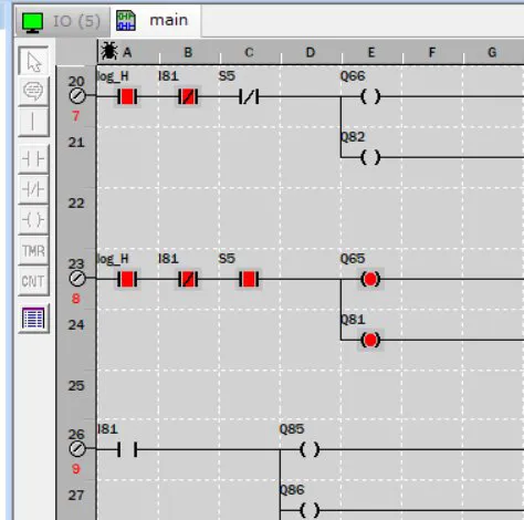
Next, we wrote a small program to observe CANbus activity.
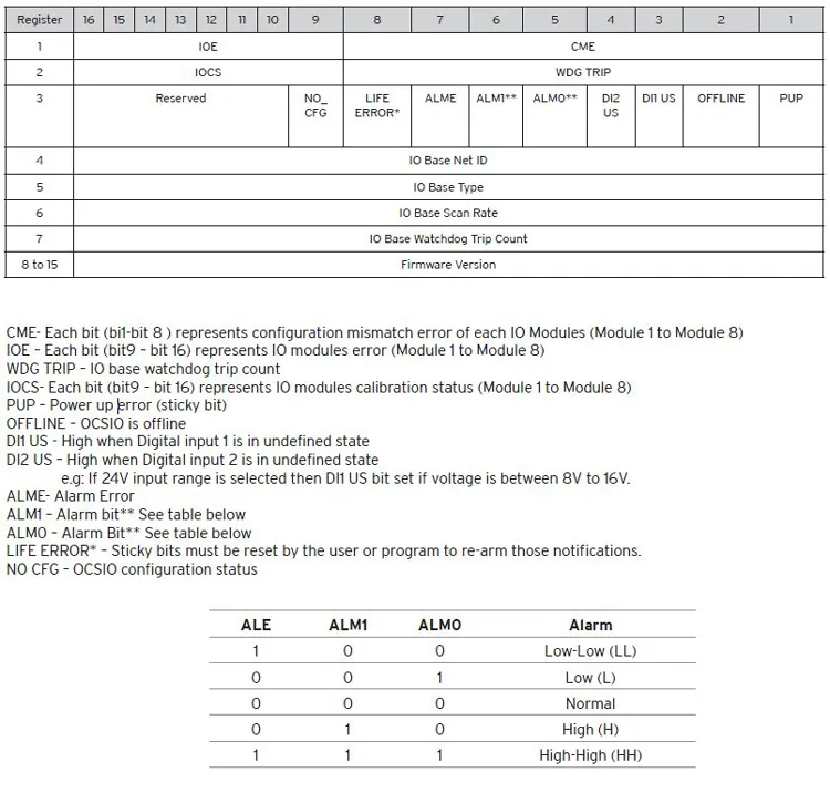
The diagnostic data from the CANbus base unit is shown below; refer to the table for its interpretation.
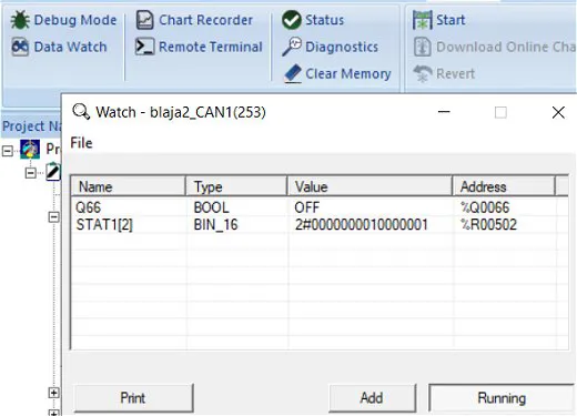
In a real application, you would typically use these diagnostics and handle them in your program.
The final step is to create an HMI screen for the CANbus peripheral.
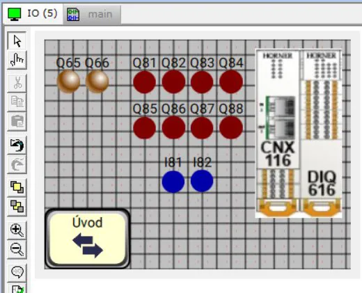
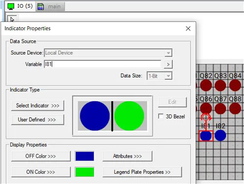
Declare the individual inputs and outputs—for example, I81 is the first input on the connected I/O module behind the base.
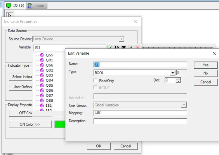
Assign outputs to indicators.
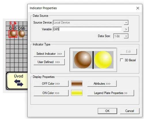
And it works.
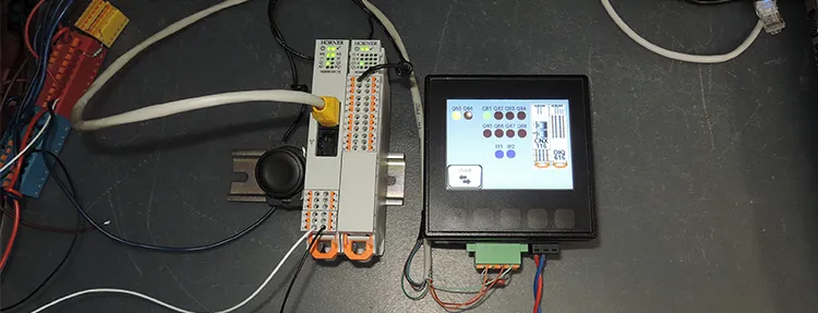
The inputs work as well, and everything can be tested.
Everything runs as expected.
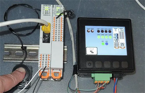
Watch the video demonstration (2 minutes).
Conclusion:
Everything works right away—just be careful with the bus speed. At higher speeds, these peripherals do not function properly, although this is not mentioned in the manual. Horner has promised to address this. Once configured correctly, however, everything runs smoothly without further issues.
Jaroslav Blažek
Interested in Horner products?
Contact our local sales representatives—they’ll be happy to show you the equipment in person.
Learn more about Horner in other articles and reviews:
- Overview of PLCs with HMI and I/O—product ranges, capabilities, and advantages
- 7 reasons to choose Horner Automation panels
Recommended products16
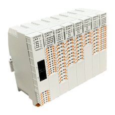
OCS-I/O – modular CsCAN I/O system for HORNER PLCs
272,25 EUR Incl. VAT

CANopen – license for Horner PLC HMI controllers X4, X7 and X10
54,45 EUR Incl. VAT
HORNER X2 PLC HMI controller with 2.2″ monochrome screen, analog / digital inputs and outputs
335,17 EUR Incl. VAT
SmartMod – remote Modbus RTU I/O modules for HORNER PLCs
234,74 EUR Incl. VAT
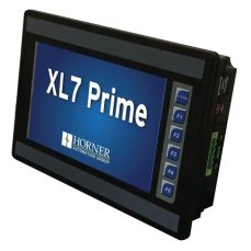
HORNER XL7 Prime PLC HMI controller with 7″ colour touchscreen, analog / digital inputs and outputs
1 747,24 EUR Incl. VAT
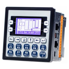
HORNER XLE PLC HMI controller with 2.2″ monochrome screen, analog / digital inputs and outputs
498,52 EUR Incl. VAT
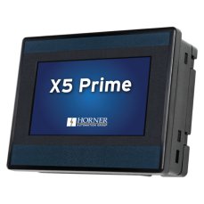
HORNER X5 Prime PLC HMI controller with 4,3″ colour touchscreen, analog / digital inputs and outputs
1 126,51 EUR Incl. VAT
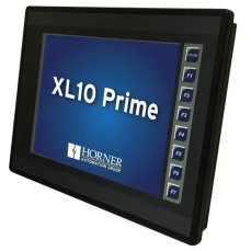
HORNER XL10 Prime PLC HMI controller with 10,4″ colour touchscreen, analog / digital inputs and outputs
2 637,80 EUR Incl. VAT
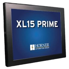
HORNER XL15 Prime PLC HMI controller with 15″ colour touchscreen, analog / digital inputs and outputs
3 447,29 EUR Incl. VAT
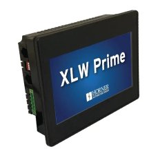
HORNER XLW Prime PLC HMI controller with 7″ colour touchscreen, analog / digital inputs and outputs
1 545,17 EUR Incl. VAT
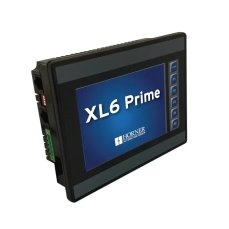
HORNER XL6 Prime PLC HMI controller with 5,7″ colour touchscreen, analog / digital inputs and outputs
1 375,77 EUR Incl. VAT
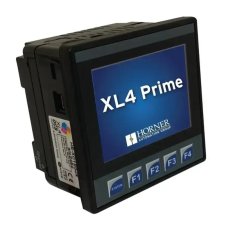
HORNER XL4 Prime PLC HMI controller with 3,5″ colour touchscreen, analog / digital inputs and outputs
1 030,92 EUR Incl. VAT

Enhanced IEC – license for Horner PLC HMI controllers XL and XL Prime
54,45 EUR Incl. VAT

J1939 – license for Horner PLC HMI controllers XL4, XLW, XL6 Prime
72,60 EUR Incl. VAT

BACnet – license for Horner PLC HMI controllers X4, X7 and X10
108,90 EUR Incl. VAT

MQTT Sparkplug – license for Horner PLC HMI controllers XL and XL Prime
54,45 EUR Incl. VAT