

Review: Horner Canvas Series PLC with Integrated HMI – Part 1: PLC

Horner PLCs with integrated HMI are new not only to our e-shop, but also to our market. We asked respected industrial automation specialist Jaroslav Blažek (blaja.cz) to explore all the functions and user-friendliness of these devices. You can find out whether he was satisfied and what it was like working with the Horner units in his review:
Explore the Horner product range
Review by Jaroslav Blažek:
A Horner PLC with HMI is therefore a 2-in-1 device. However, considering everything this device offers, we could even describe it as 4-in-1. So let’s take a look at how it works.
We won’t focus on detailed programming, as that is always somewhat specific. Instead, we’ll show the key points needed to get the device working.
Horner manufactures these PLCs with HMI in a wider range and in two series: simple devices in the Micro series and more powerful ones in the Canvas series. Remote I/O modules are also available and can be connected to the PLC.
I worked with a size 4 model from the Canvas series:
- TFT display, 65,000 colors, 320 × 240 resolution
- Dimensions: 96 × 96 mm, depth 65 mm
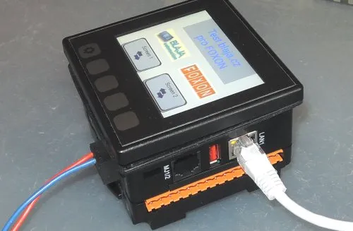
- Terminal blocks and various ports on each side—it is almost surprising how much they managed to fit in.
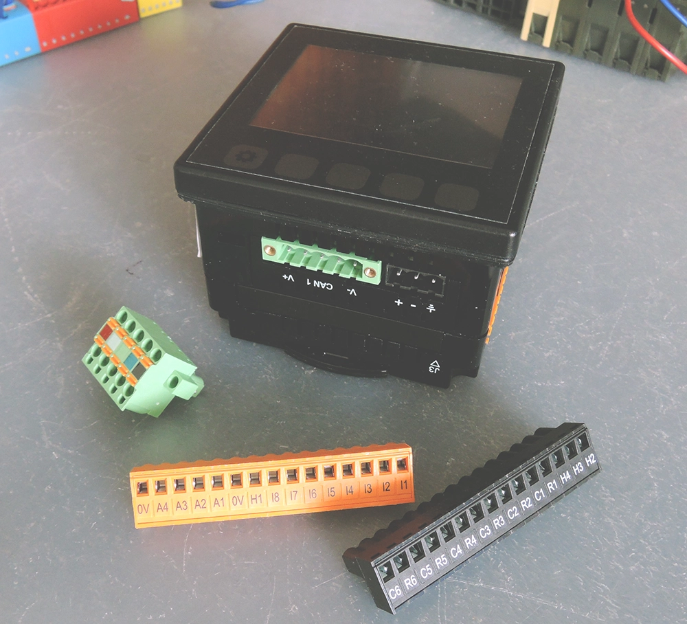
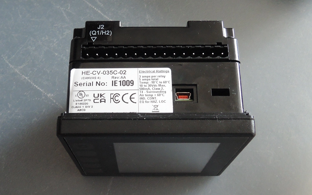
The final model designation, in this case 02, indicates which I/O combinations the PLC supports. These include various I/O combinations plus Pt100 temperature measurement, thermocouples, and universal analog inputs.

Also note the USB port.
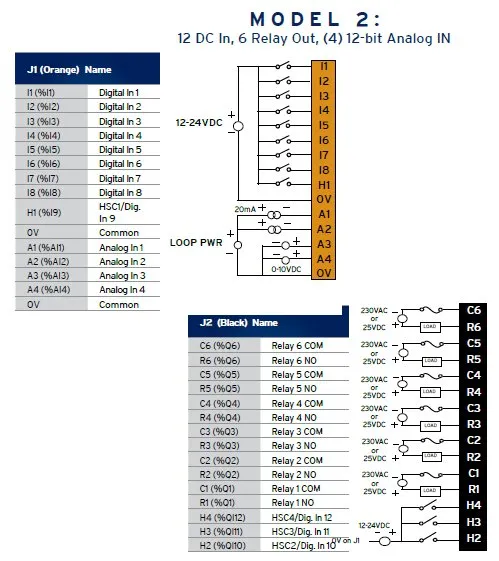
Our “02” version is equipped with 12× IN (4× HSC), 6× relay OUT, and 4× 12-bit analog IN.
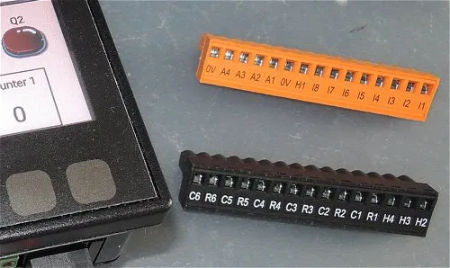
To keep things clear, the terminal block is labeled according to type, so it should be almost impossible to mix things up. Although...?
After installing the software, the first step is to connect to the PLC, as with other devices. In the system menu (left button with the gear icon), select Ethernet. In addition, connection is possible via serial port, modem, and also USB, as we will see later.
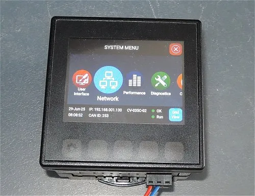
Ethernet branches into Wi-Fi, LAN, and CAN. We do not have the Wi-Fi module installed in this PLC, so in the LAN menu we set a fixed IP address and other parameters, similar to a PC network card. We are not interested in the rest for now. Only once the connection works can we start “playing around” and adjusting settings.
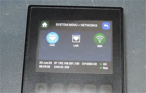
Once the IP address is set on the PLC, connect it to the network and get started.
But it will take a little while before we have this screen and program displayed.
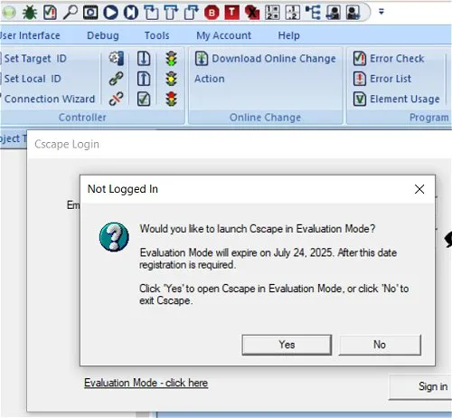
Before I registered the Cscape software for application development (without registration it runs in a one-month time-limited trial mode), I worked with the one-month trial version. After registering the software, the message shown below disappears.
First, the hardware configuration must be set: the type, series, and model of our PLC. Most importantly, however, the LAN1 port configuration must be set.
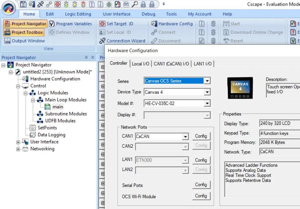
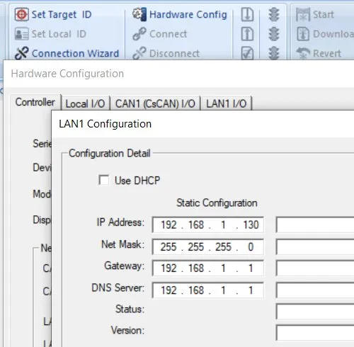
Here we enter the PLC IP address and other parameters that were set manually on the PLC. This is important. The connection and communication can be configured in several ways, but this seemed to us the simplest and fastest. Besides, an Ethernet cable is usually lying around in every drawer.
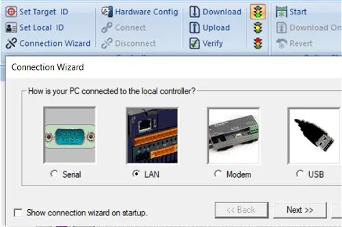
Finally, there is a wizard where we define how and through which port we will connect to the PLC.
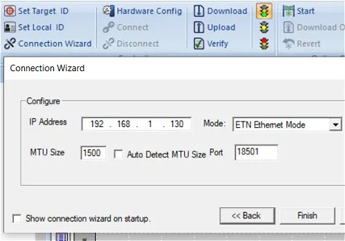
We will connect to this PLC address. If there are multiple PLCs on the network, this is where we select the address of the one we want to connect to.
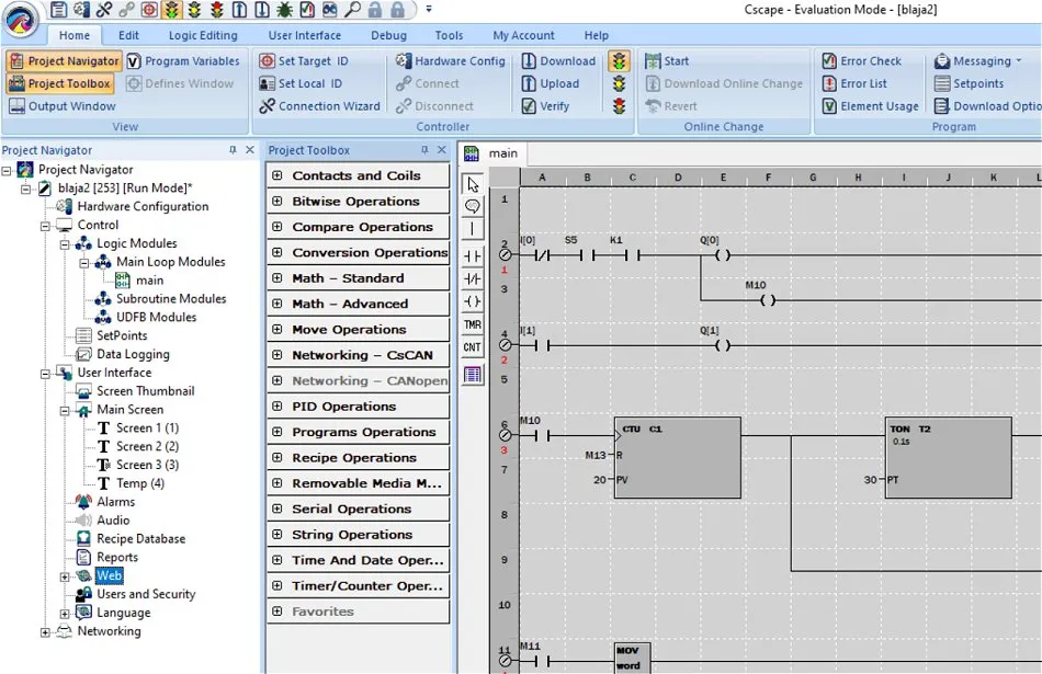
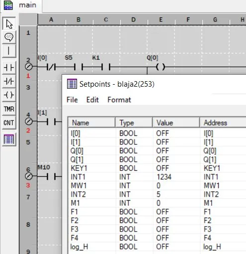
We create a short program using a few variables, a counter, and a variable value transfer. It is simple and similar to other PLCs. There is no need to go into detail here, as it is well described in the manual. We will just show the “variable declaration,” where variables can be given different names.
In the table, we declare what we will use: which variables and which types.
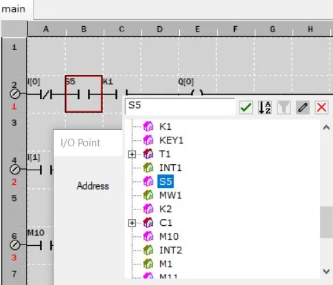
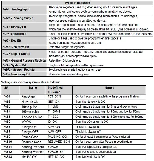
For example, S5 is a system variable of type Boolean. It changes periodically from L to H every second: 500 ms H and 500 ms L, and so on. The exact variable address is set using the function under the small pencil icon on the right.
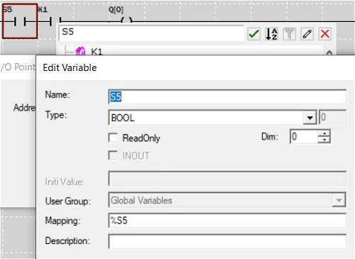
We can choose any name, such as “flasher” or anything else. To make it easier to remember, we kept the system designation S5. We then map it to the system variable %S5. The syntax must be exact.
The table makes it clear: the first half describes groups of system variables, while the second half describes the meaning of system bits. This is just to give an idea; the rest of the tables are in the manual.
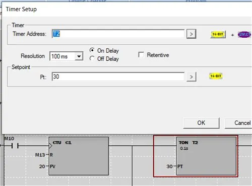
Here is an example of timer settings. Similar to other PLCs, the time base is set roughly, while the rest is handled by the variable. 30 = 3.0 seconds.
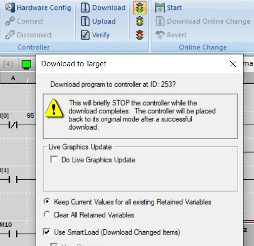
PoIf the VERIFY check shows no errors, we upload everything to the PLC using DOWNLOAD. And that’s it.
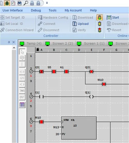
The program can then be debugged online using DEBUG (the bug icon in the upper left).
Conclusion:
This review describes only working with the PLC. The HMI part is covered in the second part. There you will also see a test of the web server, which worked surprisingly immediately and flawlessly.
Author: Jaroslav Blažek
Recommended products16

J1939 – license for Horner PLC HMI controllers XL4, XLW, XL6 Prime
72,60 EUR Incl. VAT
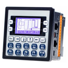
HORNER XLE PLC HMI controller with 2.2″ monochrome screen, analog / digital inputs and outputs
498,52 EUR Incl. VAT
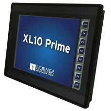
HORNER XL10 Prime PLC HMI controller with 10,4″ colour touchscreen, analog / digital inputs and outputs
2 637,80 EUR Incl. VAT
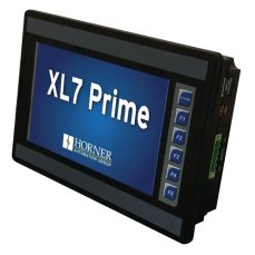
HORNER XL7 Prime PLC HMI controller with 7″ colour touchscreen, analog / digital inputs and outputs
1 747,24 EUR Incl. VAT
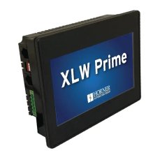
HORNER XLW Prime PLC HMI controller with 7″ colour touchscreen, analog / digital inputs and outputs
1 545,17 EUR Incl. VAT
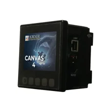
HORNER CANVAS 4 PLC HMI controller with 3.5″ colour touchscreen, analog / digital inputs and outputs
1 066,01 EUR Incl. VAT
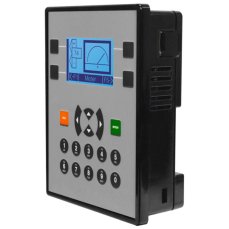
HORNER X2 PLC HMI controller with 2.2″ monochrome screen, analog / digital inputs and outputs
335,17 EUR Incl. VAT
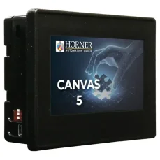
HORNER CANVAS 5 PLC HMI controller with 4.3″ colour touchscreen, analog / digital inputs and outputs
1 161,60 EUR Incl. VAT
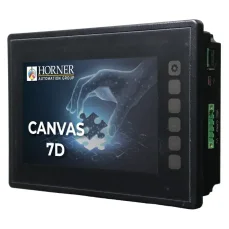
HORNER CANVAS 7D PLC HMI controller with 7″ colour touchscreen, analog / digital inputs and outputs
1 840,41 EUR Incl. VAT
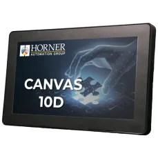
HORNER CANVAS 10D PLC HMI controller with 10.1″ colour touchscreen, analog / digital inputs and outputs
1 978,35 EUR Incl. VAT
HORNER X10 PLC HMI controller with 10″ colour touchscreen, analog / digital inputs and outputs
1 363,67 EUR Incl. VAT

HORNER X7 PLC HMI controller with 7″ colour touchscreen, analog / digital inputs and outputs
936,54 EUR Incl. VAT

Cscape 10 – application development software for Horner PLC HMI controllers
WebMI – software for remote monitoring of Horner PLC HMI controllers
96,80 EUR Incl. VAT

CANopen – license for Horner PLC HMI controllers X4, X7 and X10
54,45 EUR Incl. VAT

MQTT Sparkplug – license for Horner PLC HMI controllers XL and XL Prime
54,45 EUR Incl. VAT