

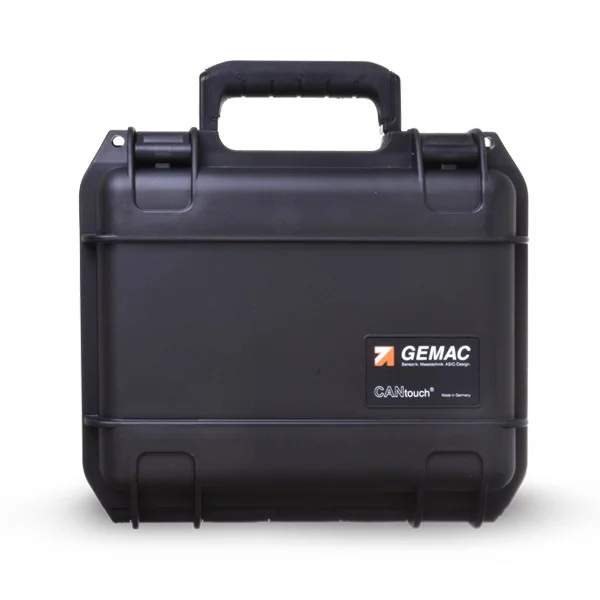


CANtouch® - handheld diagnostics and tester for CAN, CANopen, DeviceNet and SAE J1939 networks

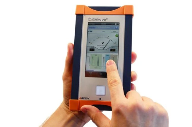
GEMAC portable diagnostic device for CAN, CANopen, DeviceNet and SAE J1939 networks. Signal and traffic monitoring without a PC, touchscreen display and up to 6 hours’ battery life during measurement. Complete PR-22580-81 set with adaptors and carrying case. Six basic applications; additional functions available as separate licences. More
Code: PR-22580-81
GEMAC portable diagnostic device for CAN, CANopen, DeviceNet and SAE J1939 networks. Signal and traffic monitoring without a PC, touchscreen display and up to 6 hours’ battery life during measurement. Complete PR-22580-81 set with adaptors and carrying case. Six basic applications; additional functions available as separate licences. More
Code: PR-22580-81
Portable CAN diagnostics
Get an overview of the CAN network status
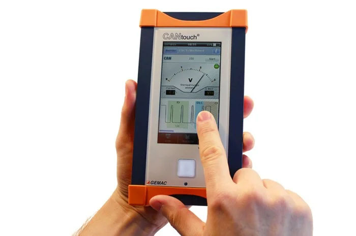
CANtouch measures electrical signals and bus data traffic. The touchscreen, built-in battery and clear display of results allow you to work on-site without needing to connect to a computer.
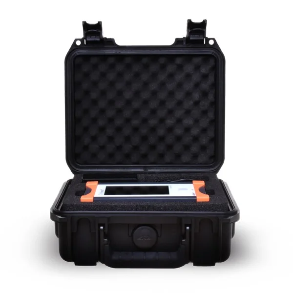
A complete set including adaptors and a service case. Additional measurement functions are activated via separate licences.
Please send us the bus type, a description of the problem and the required functions. We will recommend the appropriate licences and connections.
Applications
Commissioning, maintenance and troubleshooting
A single device for checking wiring, monitoring operation and performing detailed signal measurements. The scope of diagnostics is determined by the activated licences.
New installation
Check the cabling, bus termination and data rate. Verify signal conditions before handing over the installation.
Fault during operation
Monitor bus load, error frames and voltage. With a Node Measurement licence, compare the signal quality of individual nodes.
Regular maintenance
Save the results by machine and project. You can use the archived values and screenshots for later comparison and documentation.
Video
CANtouch in practice
Open the video on YouTubeAutomatic test
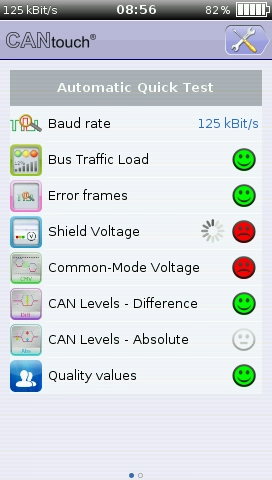
A quick overview of the bus status
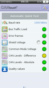
The automatic quick test detects the data rate and continuously evaluates the measured values. Coloured symbols flag problems; tap a symbol to view the details.
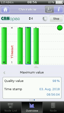
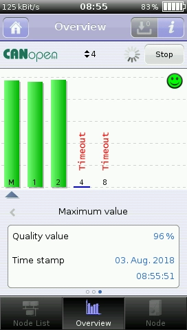
The overview also provides an overall assessment of the bus nodes’ signal quality without a Node Measurement licence on the tester. Detailed measurement of an individual node requires a licence for the relevant protocol.

The rating thresholds can be customised in the XML file and saved with the project. The green rating relates to the measurements actually taken and the thresholds set.
Basic functions
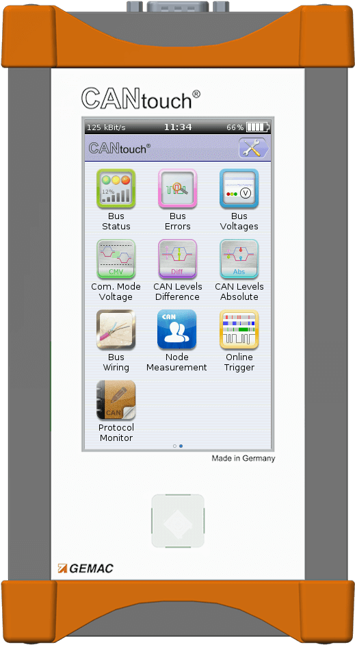
Six measurement applications included as standard
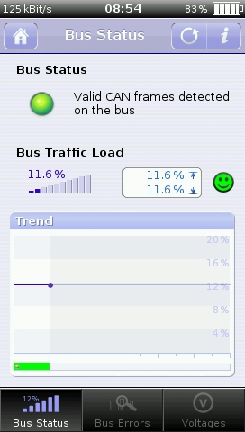
Bus status
Bus Status
Detection of bus traffic and bus states. Bus load from 0-100 % is displayed over time, including minimum and maximum values.

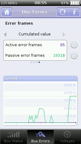
Error frames
Bus Errors
Counting active and passive error frames. The current frequency, minimum, maximum and time trend will help identify unstable operation.
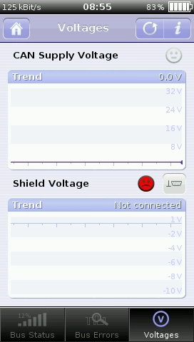
Bus voltage
Bus Voltages
Measurement of the CAN supply voltage and shield voltage, including changes over time.
Common-mode voltage
Common Mode Voltage
Analysis of potential differences between participants. This helps to identify problems with earthing and common signal reference.
CAN differential levels
CAN Levels Difference
Measurement of the voltage difference between CAN_H and CAN_L in both the dominant and recessive states.
CAN absolute levels
CAN Levels Absolute
Measurement of the CAN_H and CAN_L voltages relative to the reference earth. This provides a further insight into the electrical state of both signal lines.
Licence
Optional functions for your measurement task
Four further types of measurement are activated via a licence. For Node Measurement, a licence must be selected separately for each protocol.

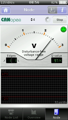
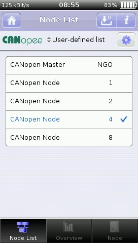
Measuring individual nodes
Node Measurement
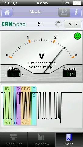
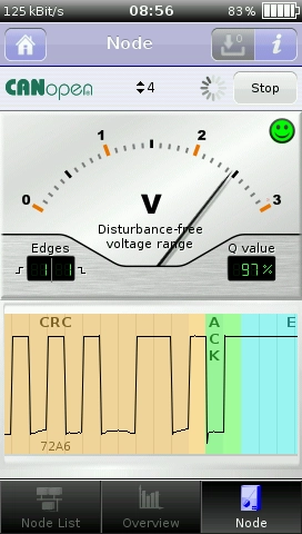
Signal quality, edge steepness, noise margin and an oscilloscope display of telegrams. Select a licence for your network protocol.
Wiring test
Bus Wiring
Detecting short circuits and open circuits, checking terminations, measuring loop resistance and cable length. The guide walks you through each step of the test.
Capturing intermittent faults
Online Trigger
Longer monitoring with custom thresholds for both physical values and logical errors. An audible alert and the display of the faulty telegram will help you pinpoint the moment the fault occurred.

Receiving and sending telegrams
Protocol Monitor
Reception, transmission of messages and sequences, symbolic decoding and Trace recording with start and stop conditions.
Examples of measurements
From a network overview to an individual signal waveform


Online Trigger time resolution
Selecting 10 ms, 100 ms, 1 s, 30 s or 1 min determines both the time resolution and the length of the history displayed. The instrument displays a maximum of 10,000 cycles. Once this limit is reached, the oldest records are overwritten; the longest displayed period corresponds to approximately one week.
Measurement documentation
Settings and results saved by project
Store separate bus settings, a node list and assessment limits for each machine. Load the appropriate project for the next measurement.
- Automatic detection or manual setting of the baud rate and bit timing.
- Select either CAN_V− or the external ground connection as the reference ground.
- Listen Only or Bus Active mode, depending on the task and connection conditions.
- Archive node measurements and Online Trigger results for later viewing on the instrument or on a PC.
- Up to 100 PNG screenshots per project. If the limit is exceeded, the oldest screenshots are overwritten.
- USB data transfer; the device appears as a drive.
Scope of delivery
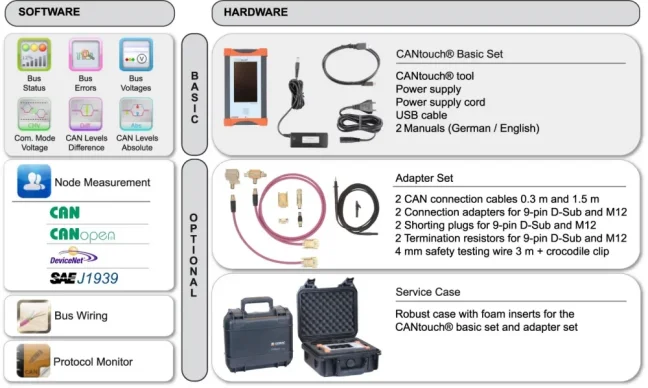
PR-22580-81 Complete Set
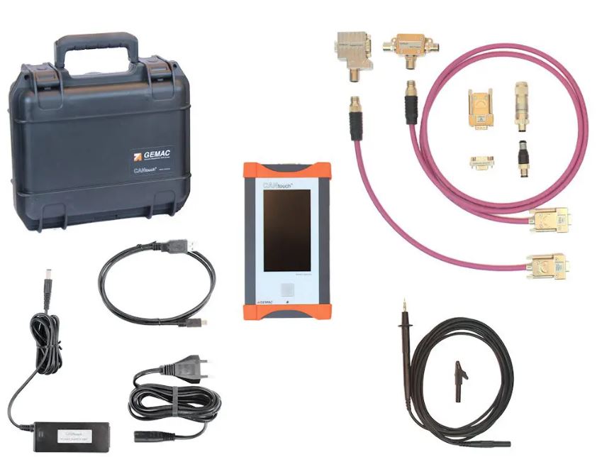
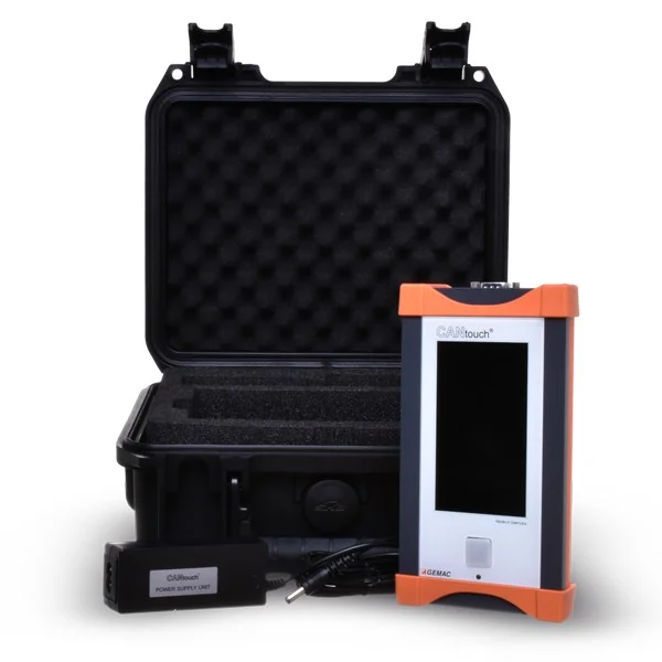
The device, connection kit and a sturdy case for transporting it between machines.
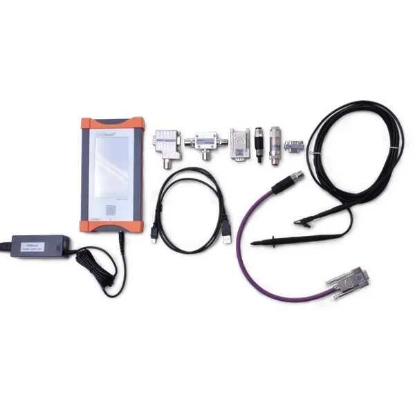
- PR-22580-00 Basic Set: CANtouch, SAW-14.0-2500 power supply, mains cable, USB cable and manuals in German and English.
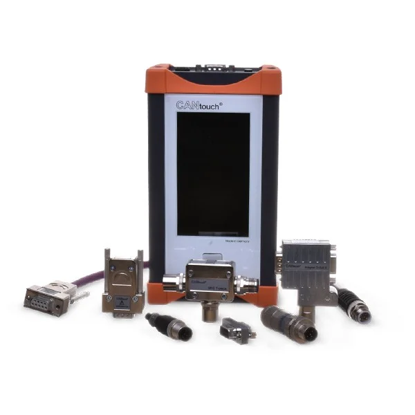
- PR-22580-10 adapter set: CAN connection cables (0.3 m and 1.5 m), 2× D-Sub 9 / 1× M12 adapter, M12 T-piece, M12 and D-Sub 9 shorting connectors, M12 and D-Sub 9 terminating resistors, safety test lead and alligator clip.
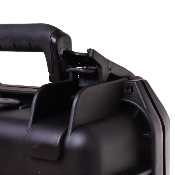
- PR-22580-50 service case: a case with foam padding for the device and adaptors.
Portable operation
Standalone measurement without a laptop
The built-in Li-ion battery powers the device for up to 6 hours during measurement. The display showing the remaining battery capacity and time makes it easier to plan your work.
Actual battery life depends on usage and settings. The device has an aluminium casing and an IP20 rating. The operating temperature range is +5 to +40 °C; protect it from water and condensation. Use the supplied power supply.
FAQ
Practical questions
Do I need a computer to take measurements?
No computer is required for on-site operation and measurement. CANtouch has its own display and battery. Use a computer to transfer results, analyse them further and install updates.
Does the complete set include all the licences?
No. The PR-22580-81 includes the basic instrument, adaptors and a case. Six basic measurement applications are included with the instrument; additional functions are activated via separate licences.
Which licence should I choose for node measurement?
Node Measurement has separate licences for CAN, CANopen, DeviceNet and SAE J1939. The SAE J1939 licence includes ISOBUS and NMEA 2000. Please let us know which protocol you are using and the measurements required.
Is it possible to try out the extension first?
Yes. Optional features can be activated on a one-off basis for 30 days. Once the trial period has expired, a suitable licence is required for continued use.
How do I create measurement documentation?
Save screenshots as PNG files in the project. Transfer node measurement archives and Online Trigger files via USB and open them in the CAN-Bus Tester 2 programme on your PC. Protocol Monitor logs can then be viewed in CANvision.
How do I update the firmware?
First, back up your settings and results. Copy the PKG file to the root folder of the CANtouch drive and run the update via the device menu as per the instructions. Leave the file name unchanged, including removing any extension such as (1) that the browser adds when the file is downloaded repeatedly.
Downloads
Documentation and software for working with results
In the ‘Downloads’ section, you will find the datasheet, user manual and an overview of GEMAC tools: the device firmware, a PC programme for measurement archives, CANvision for protocol logs and a symbol editor.
Documents and software to download
Documentation for the device and tools for transferring, displaying and further processing the results.
Analysis on a computer
Use CAN-Bus Tester 2 for the instrument’s measurement archives. CANvision displays protocol lists and Trace records; these data can be viewed in Trial mode. Other PC software functions and permanent CANtouch measurement licences are separate matters.
CANtouch Technical Specifications
| Device and bus systems | |
|---|---|
| Product | GEMAC CANtouch Complete Set / PR-22580-81 |
| Operating method | A standalone, portable device with a touchscreen and a rechargeable battery |
| Interface languages | German, English |
| Bus | CAN in accordance with ISO 11898-2, CANopen, DeviceNet, SAE J1939; ISOBUS and NMEA 2000 under the relevant SAE J1939 licence |
| Standard transmission speeds | 10; 20; 50; 100; 125; 250; 500; 800; 1,000 kbit/s, depending on the protocol |
| Additional user-defined data rates | 5; 33.3; 62.5; 75; 83.3; 200 kbit/s |
| Bit timing | Adjustable tq, sampling point and SJW; automatic baud rate scan |
| Bit sampling | 64-fold, 10,240 sampling points |
| Functions and recording | |
| Basic applications | Bus Status, Bus Errors, Bus Voltages, Common Mode Voltage, CAN Levels Difference, CAN Levels Absolute |
| Optional applications | Bus Wiring, Node Measurement by Protocol, Online Trigger, Protocol Monitor |
| Bus load | 0-100 %, trend over time, minimum and maximum |
| Error frames | Distinction between active and passive error frames, their frequency and trend over time |
| Online Trigger | Resolution: 10 ms, 100 ms, 1 s, 30 s and 1 min; maximum of 10,000 time cycles |
| Protocol Monitor | Receiving and transmitting telegrams, sequences, symbolic decoding and Trace recording with start and stop conditions |
| Projects and documentation | Bus settings, participant lists, evaluation thresholds and archives; up to 100 PNG images per project |
| Power supply and connections | |
| Battery | Built-in rechargeable Li-ion battery |
| Battery life | Up to 6 hours of measurement; up to 36 hours of use; up to 500 hours on standby. Depends on usage and settings. |
| Charging | Approximately 80% in 1 hour; fully charged in approximately 2 hours |
| External power supply | 14 V DC SELV; supplied 35 W SAW-14.0-2500 power supply, internal 2.5 A fuse |
| CAN connection | 9-pin D-Sub |
| PC connection | USB 2.0 Full Speed, galvanically isolated; USB Mass Storage for data transfer |
| Reference ground | CAN_V− or external earth connection |
| Mechanical design and environment | |
| Housing | Aluminium body, glass cover |
| Degree of protection | IP20, in accordance with EN 60529 |
| Dimensions of the device | 186 × 102 × 37 mm |
| Weight of the device | Approximately 860 g |
| Operating temperature | +5 to +40 °C |
| Storage temperature | −20 to +60 °C |
| Environment | Non-condensing |
Measuring ranges and accuracy
| Measured quantity | Range | Resolution | Typical accuracy |
|---|---|---|---|
| Signal quality | 0.0-100.0 % | 0.1 % | - |
| Edge steepness | 0/64-64/64 | 1/64 | - |
| Noise margin | −0.75 to +3.25 V | 0.05 V | 1.90 % ±100 mV |
| Differential voltage | −0.75 to +3.25 V | 0.01 V | 0.50 % ±10 mV |
| Absolute voltage | −5.00 to +10.00 V | 0.05 V | 0.50 % ±50 mV |
| Shield voltage | −10.0 to +1.0 V | 0.1 V | 0.25 % ±100 mV |
| CAN supply voltage | 0.0-32.0 V | 0.1 V | 0.25 % ±100 mV |
| Loop resistance | 0-100 Ω | 0.1 Ω | 0.85 % ±0.2 Ω |
| Loop resistance | 100-1 000 Ω | 1 Ω | 0.85 % ±2 Ω |
| Cable length | 2-1,000 m | 1 m | 5 % ±2 m |
The accuracy values for voltage measurements are relative to the calibrated input. Length measurements are based on a signal propagation time of 4.5 ns/m. The availability of measurements depends on the licences activated; cable testing requires following the procedure set out in the guide.
Highlighted items are mandatory.

License for measuring SAE J1939 network nodes for the CANtouch® tester.
653,40 EUR Incl. VAT

License for measuring CANbus network nodes for the CANtouch® tester.
1 241,46 EUR Incl. VAT

CANopen network node measurement licence for CANtouch® devices
1 045,44 EUR Incl. VAT

CANbus network node measurement licence for CANtouch® devices
653,40 EUR Incl. VAT

License "Online Trigger" for CANtouch® tester
653,40 EUR Incl. VAT

License „Bus Wiring“ for CANtouch® tester
653,40 EUR Incl. VAT

License „Protocol monitor“ for CANtouch® tester
653,40 EUR Incl. VAT
Related products7
License for measuring SAE J1939 network nodes for the CANtouch® tester.
653,40 EUR Incl. VAT
License for measuring CANbus network nodes for the CANtouch® tester.
1 241,46 EUR Incl. VAT
CANopen network node measurement licence for CANtouch® devices
1 045,44 EUR Incl. VAT
CANbus network node measurement licence for CANtouch® devices
653,40 EUR Incl. VAT
License "Online Trigger" for CANtouch® tester
653,40 EUR Incl. VAT
License „Bus Wiring“ for CANtouch® tester
653,40 EUR Incl. VAT
License „Protocol monitor“ for CANtouch® tester
653,40 EUR Incl. VAT