

CAN-Bus Tester 2 - CAN network diagnostic tester with PC analysis
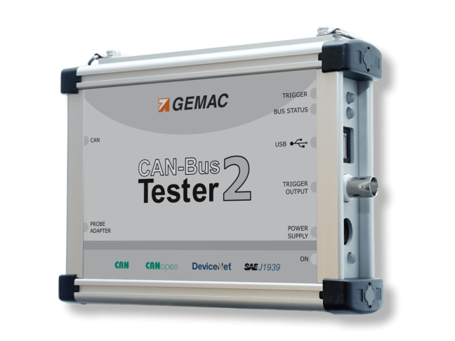


CAN-Bus Tester 2 - CAN network diagnostic tester with PC analysis

GEMAC diagnostic device for checking cabling and CAN signal quality, with results analysed on a PC via USB. PR-22517-10 basic kit with a case and six sets of adaptors. CANopen, DeviceNet, SAE J1939 and protocol monitors subject to licence. Please check the compatibility of the USB driver with Windows before use. More
Code: PR-22517-10
GEMAC diagnostic device for checking cabling and CAN signal quality, with results analysed on a PC via USB. PR-22517-10 basic kit with a case and six sets of adaptors. CANopen, DeviceNet, SAE J1939 and protocol monitors subject to licence. Please check the compatibility of the USB driver with Windows before use. More
Code: PR-22517-10
CAN diagnostics with PC evaluation
Get an overview of CAN network quality
The CAN-Bus Tester 2 measures electrical signals and bus data traffic. On your computer, you can compare the signal quality of individual nodes, capture intermittent faults and prepare a measurement report for the customer or maintenance team.
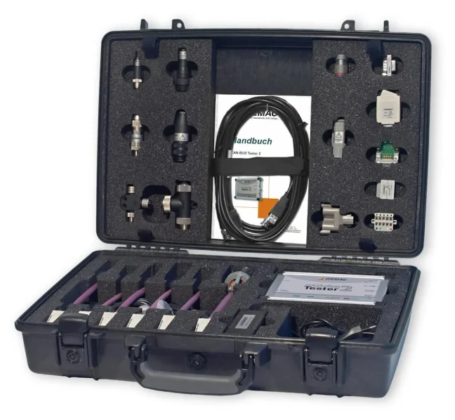
The PR-22517-10 basic kit includes CAN measurement, connection accessories and a case. Additional buses and the Protocol Monitor are activated via separate licences.
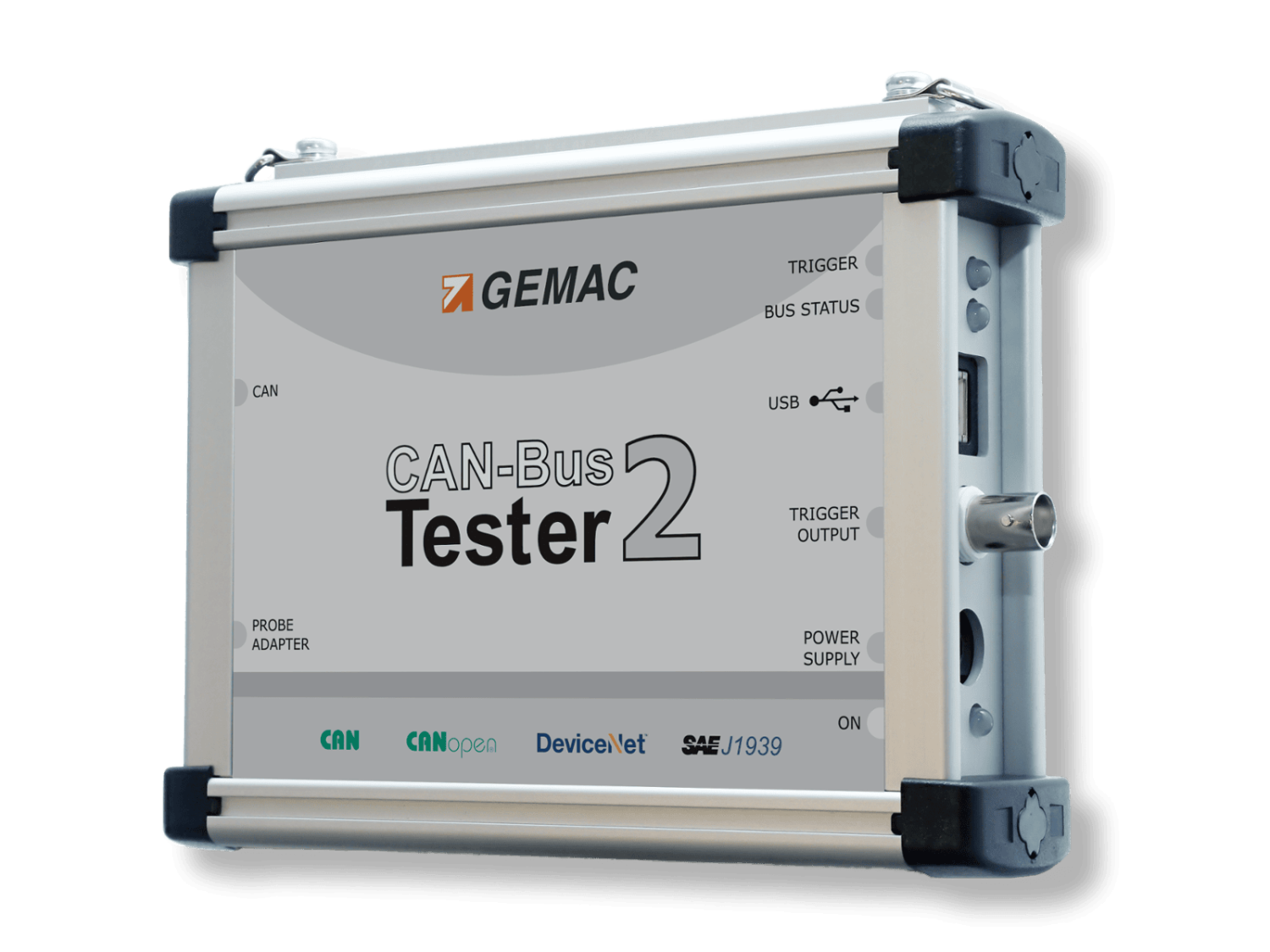
Please let us know the bus type, the connectors used and the measurements required. We will check the necessary licences and the requirements for connecting to a computer.
Uses
For new and older machines with CAN bus networks
From checking the cabling to long-term monitoring of operations. You can store the measurement results by location and time of measurement and compare them during your next inspection.
New installation
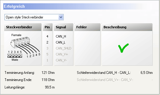
Check the wiring, termination and cable length. Once the network is running, check the bit rate and signal quality of each node.
Occasional fault
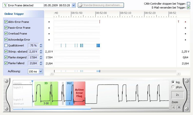
Monitor load, error frames and signal quality. Online Trigger captures the event and displays the corresponding waveform.
Handover and regular inspections
Compile a measurement report including tables, graphs and the details of both the customer and the technician. On your next visit, you can refer back to the saved results.
Video
The CAN-Bus Tester 2 in practice
Open the video on YouTubeMeasurement and analysis
One tester for measuring signal quality and communication
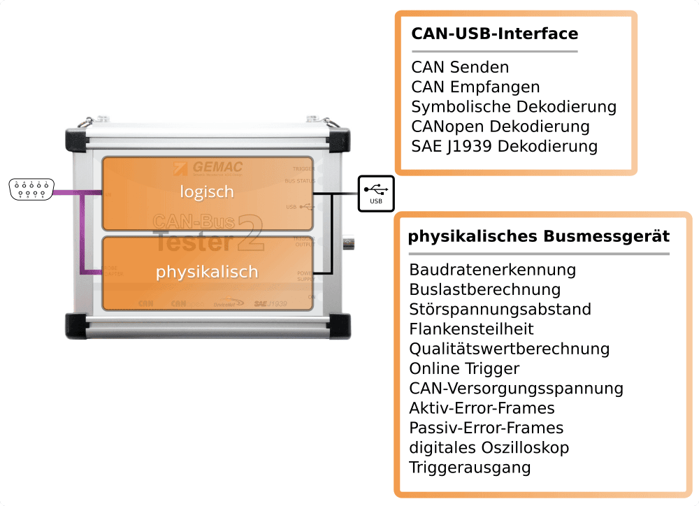
Physical measurements will reveal the margin available for electrical signals. Protocol analysis will focus on the content of the transmitted messages.
Both parts operate independently or simultaneously. When a physical error occurs, the protocol monitor recording can be stopped to relate the signal problem to the corresponding communication.
Protocol analysis requires a valid Protocol Monitor licence. The licences for bus measurement and for the Protocol Monitor are separate.
Basic functions
Measurement functions of the basic set
Cable inspection
Detection of short circuits and open circuits, termination checks, measurement of loop resistance in signal and power supply cables, and measurement of total cable length.
Node measurement
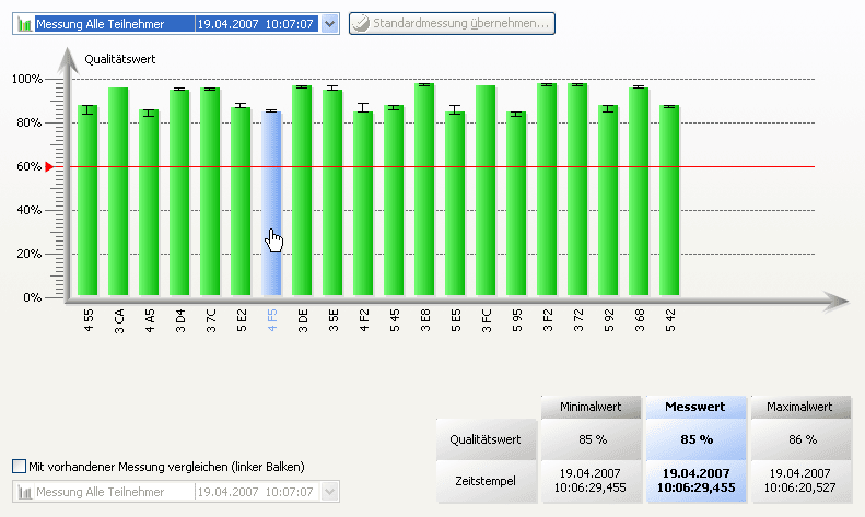
Signal quality 0-100 %, rising and falling edge steepness, and disturbance-free voltage range. Compare nodes clearly, including minimum and maximum values.
Oscilloscope display
Full-frame recording and decoding, six zoom levels and an adjustable trigger position. The BNC output allows connection to an external oscilloscope.
Online Trigger
Real-time monitoring of logical and physical errors. Adjustable thresholds for signal quality, disturbance-free voltage range and edge steepness, with display of the faulty waveform.
Bus status and load
Distinguishing between dominant and recessive states, undefined states and ongoing communication. Bus load 0-100 per cent, with minimum and maximum values.
Error frames
Real-time counting and differentiation of active and passive error frames. The log will help to link the error to the moment of an outage or increased load.
Examples of measurements
A detailed look at the network
Occasional errors and trigger conditions
Set the Online Trigger time resolution from 10 ms to 1 minute. Trigger conditions include error and overload frames, acknowledgement errors, and violations of the configured thresholds for signal quality, disturbance-free voltage range and edge steepness.
Field measurements
Examples of real CAN network measurements
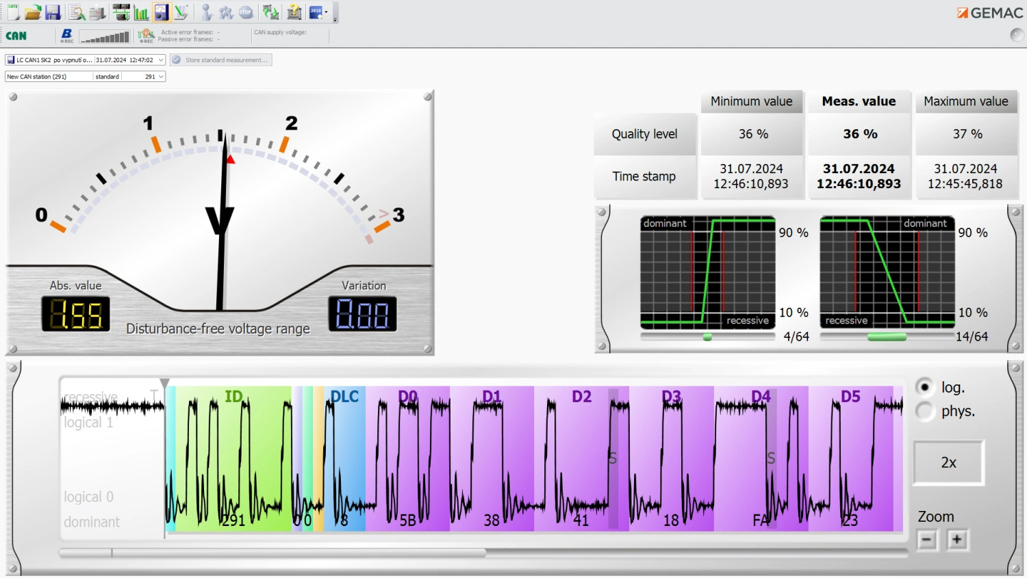
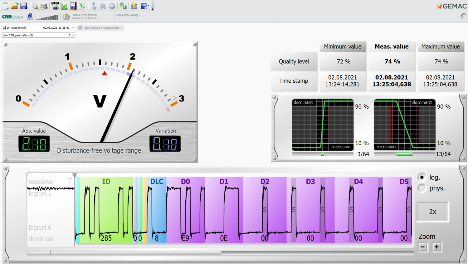
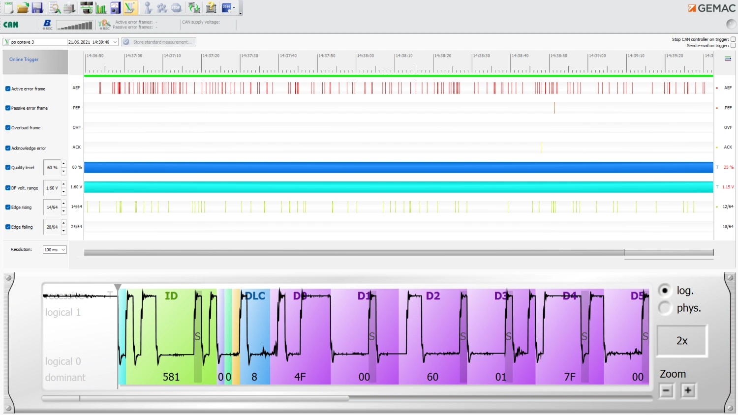
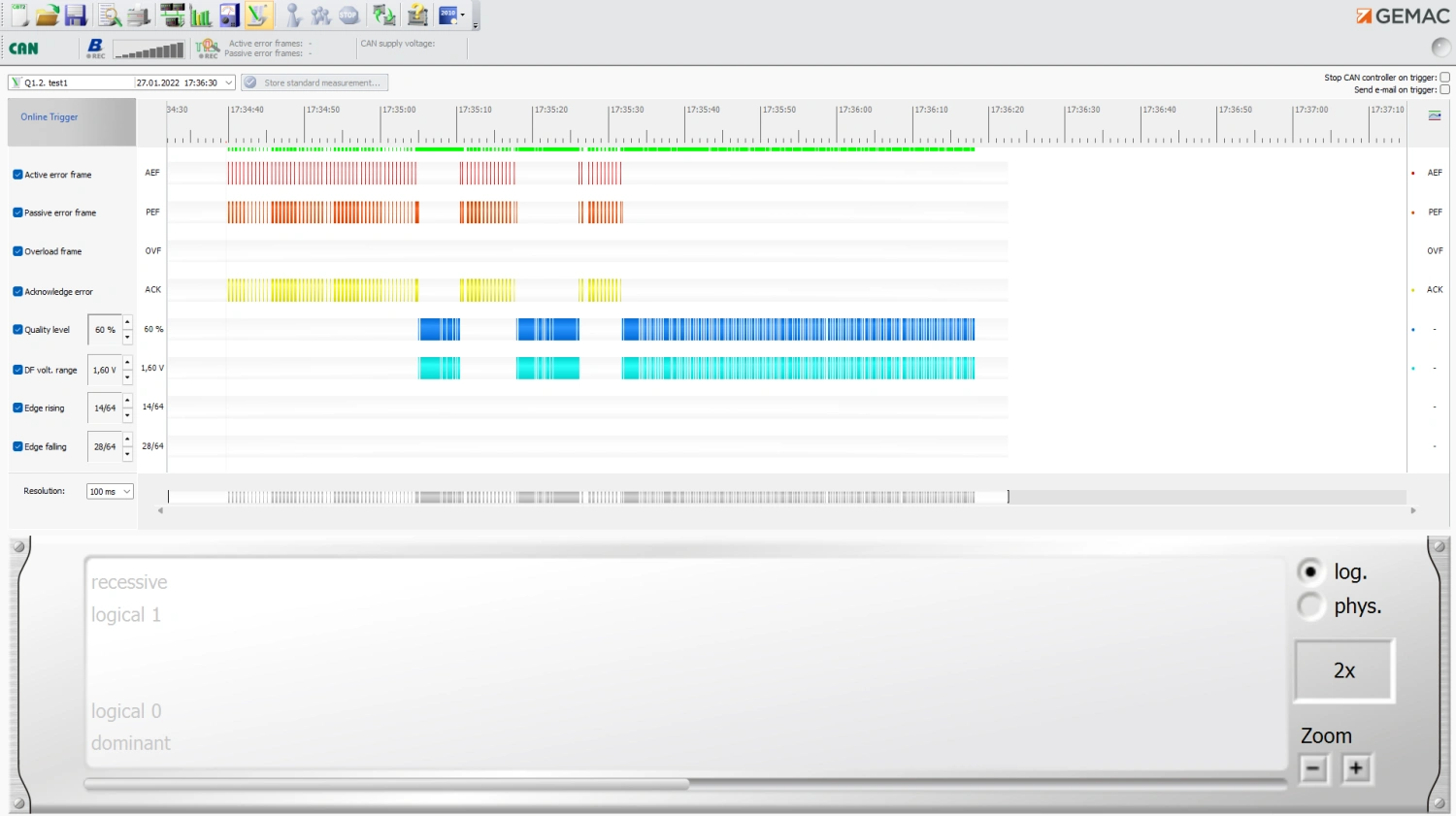
Real measurements with CAN-Bus Tester 2. Click an image to see a larger view.
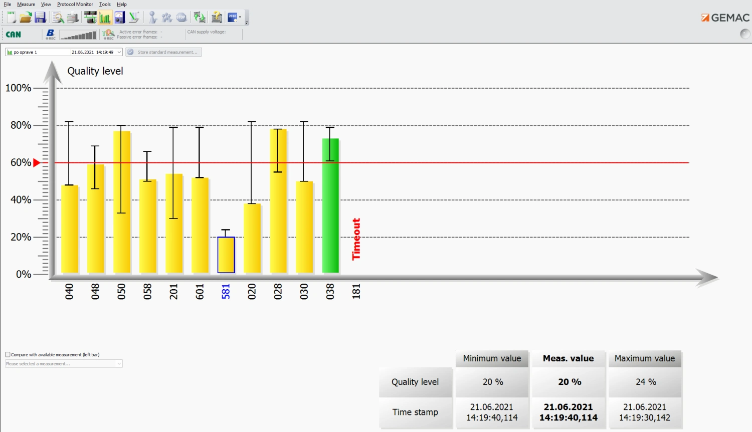
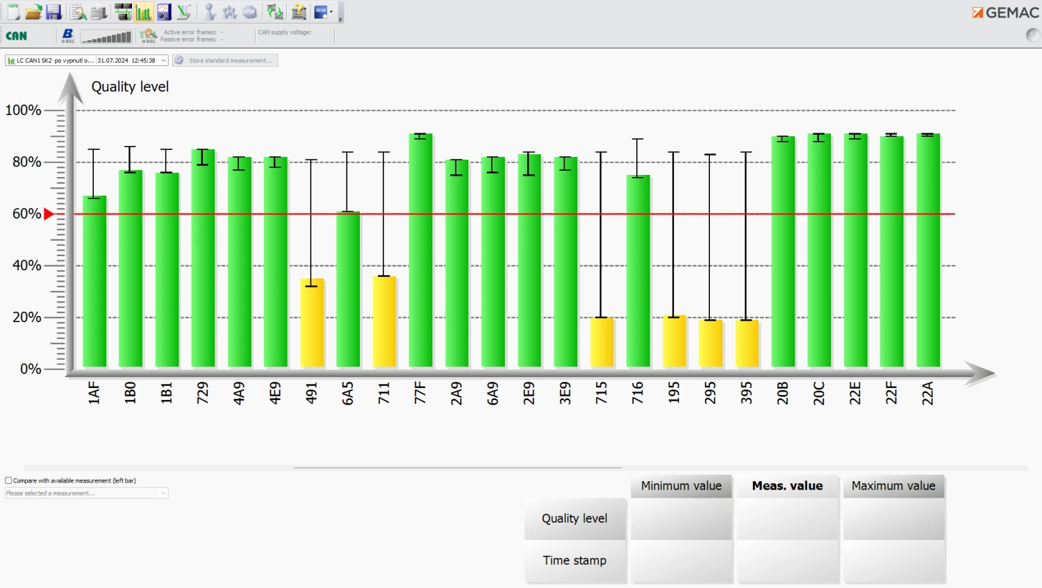
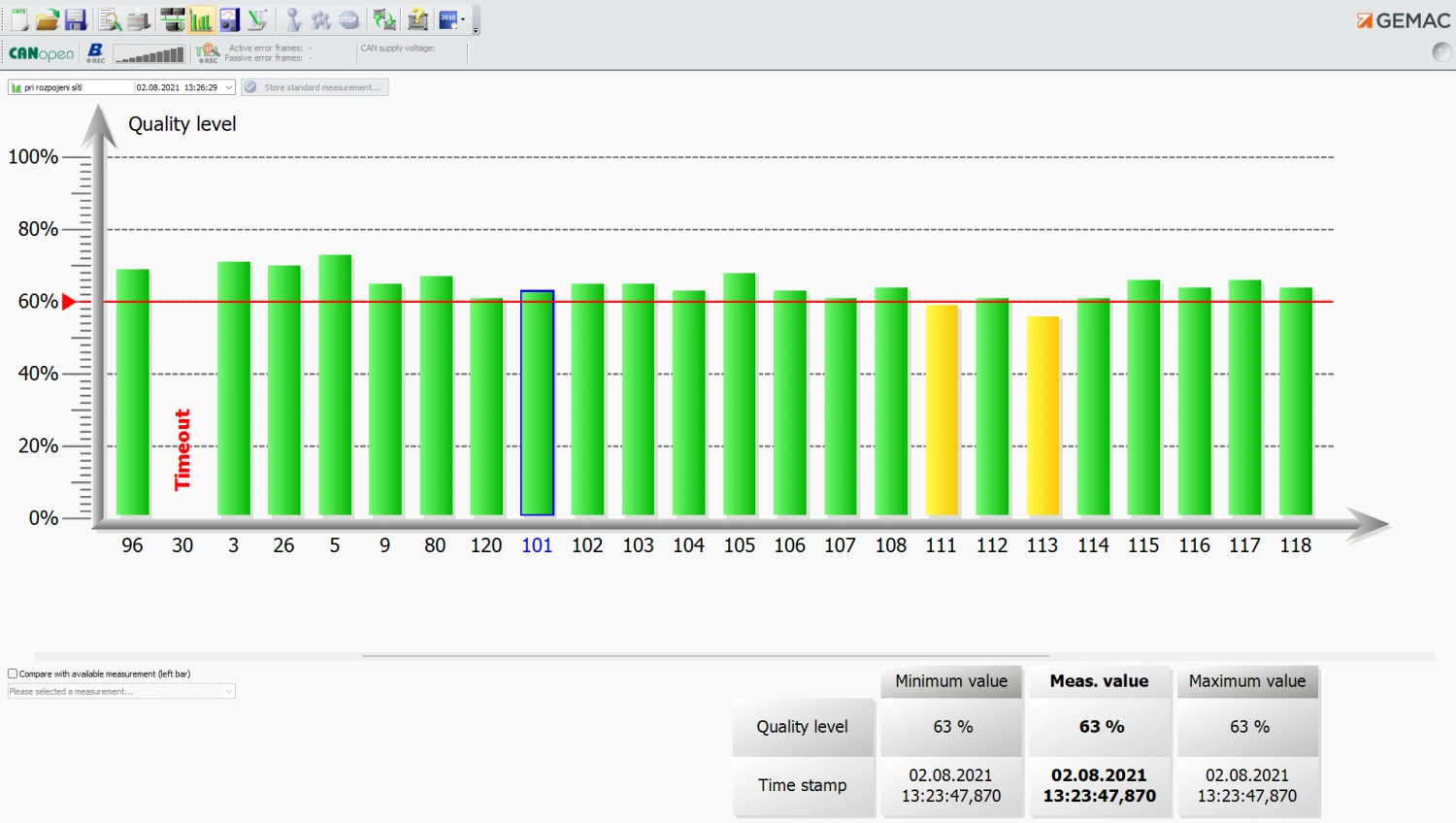
Signal quality at the stations
The bars show the signal quality at each station. You can quickly compare their condition and see where more detailed measurements are needed.
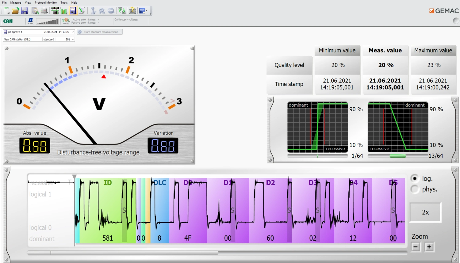
Oscilloscope waveforms at the stations
The oscilloscope waveform helps you identify the type of signal problem. It helps detect, for example, a short circuit, incorrect resistor termination or electromagnetic interference (EMI).
Long-term measurement
The long-term recording shows how often unwanted events occur in the network. It captures signal quality falling below a set threshold, incorrect rising or falling signal edges, error frames (ERROR) and other events.
Extension
Licences by protocol and task
The basic kit measures the CAN physical layer. Select bus extensions and protocol monitors separately, depending on what you need to analyse.
Other buses
- CANopen / SW-22517-01
- DeviceNet / SW-22517-02
- SAE J1939, ISOBUS and NMEA 2000 / SW-22517-03
Extends node measurement and interpretation for the selected bus.
Receiving and sending messages
- CAN: Transmission and Reception / SW-22517-10
- CANopen: Reception and Interpretation / SW-22517-11
- SAE J1939, ISOBUS and NMEA 2000: reception and interpretation / SW-22517-12
The CAN monitor can filter messages and transmit individual frames as well as pre-prepared sequences. For CANopen and SAE J1939, the licences listed are intended for reception and decoding.
Decoding the content
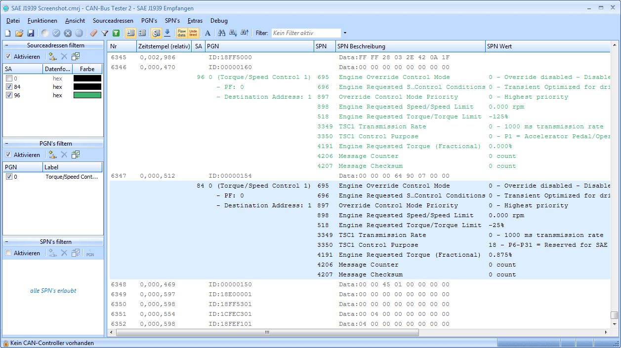
The CANopen monitor interprets, for example, SDO, PDO, NMT, Heartbeat, Emergency and Sync. The SAE J1939 monitor distinguishes between the source address, PGN and SPN parameters, including the name, value and unit.
The SAE J1939 monitor includes decoding of the ISOBUS and NMEA 2000 extensions.
Measurement documentation
Results for handover and ongoing maintenance
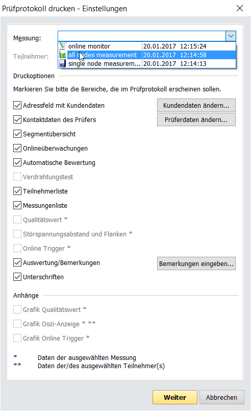
Using the measurements, you will prepare documentation in A4 format with your own letterhead, including the client’s and technician’s details, tables and graphs.
- Saving multiple measurements, specifying the location, time and type of measurement.
- Printing of the summary and detailed results based on the selected log content.
- Export measured data to a customisable CSV file.
- Export graphs and waveforms as BMP, JPG or PNG files.
- Opening measurement logs from the CANtouch device in the PC programme CBT2.
Working with the tester
Connection and measurement conditions
Control via a computer
The tester connects via a galvanically isolated USB port. The CBT2 programme, available in German or English, is used to operate the device, display waveforms and save results. The device requires an external power supply.
Windows compatibility
The PC programme requires a functioning USB driver for the CBT2. Following a Windows update or fresh installation, particularly of Windows 11, the driver may fail to load, meaning the computer will not recognise the tester. Before purchasing, please check that it works with your specific computer and its security settings; compatibility with current and future Windows updates cannot be guaranteed.
Contents of the delivery
PR-22517-10 basic set
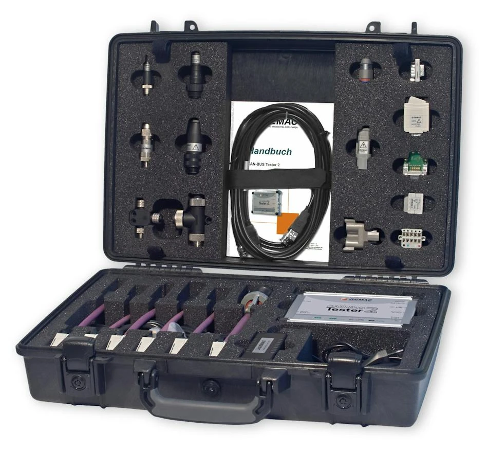
The instrument and accessories in a lockable case for transport between measurement sites.
- CAN-Bus Tester 2 with basic CAN bus measurement.
- Six sets of adaptors: D-Sub 9, Open style, M12, 7/8″, SAE J1939-11 and SAE J1939-13.
- An adapter board for connecting oscilloscope probes.
- A 3-metre USB cable and a 1.5-metre BNC cable.
- Mains power supply 100-240 V AC / 24 V DC, 500 mA; 2 m power supply cable and 1.8 m mains cable, depending on the country of use.
- User manual and a sturdy, lockable case, including keys.
- PC software CBT2, available for download in German and English.
The kits contain the appropriate connection cables and, depending on the connector type, shorting connectors, terminating resistors and T or Y splitters. Licences for additional buses and the Protocol Monitor are not included in the basic kit.
FAQ
Practical questions
Do I need a computer to take measurements?
Yes. The CAN-Bus Tester 2 is controlled from a PC via USB and does not have its own display or battery for standalone testing. Please use the supplied power supply and a pre-tested computer with a working USB driver.
What is included in the basic set?
CAN bus measurements, including cabling checks, node measurements, oscilloscope display, Online Trigger, and monitoring of status, load and error frames. Other buses and the Protocol Monitor require separate licences.
Is a bus licence sufficient for the protocol monitor as well?
No. The CANopen, DeviceNet and SAE J1939 licences extend physical measurements. A corresponding Protocol Monitor licence is required to receive and decode the protocol. For CAN, both reception and transmission are available; for the CANopen and SAE J1939 monitors mentioned, reception and interpretation are available.
Can the cabling be checked whilst the system is running?
The wiring test requires all nodes and the bus power supply to be disconnected, and the termination to be changed as instructed by the wizard. During normal operation, monitor communication and signal quality in the appropriate measurement mode.
How do I create a measurement report?
In the programme, select the required measurements and sections of the report, enter the customer’s and technician’s details, and print the document on A4 paper. Data can be exported to CSV, and graphs to BMP, JPG or PNG.
Does the tester work with the latest version of Windows?
Operation depends on the USB driver CBT2 being loaded. A Windows update or fresh installation may prevent it from working, particularly in Windows 11. Please check your specific computer before purchasing; simply installing the programme does not guarantee that the tester will connect successfully.
Download
Documentation and PC software
In the ‘Downloads’ tab, you will find the user manual, the GEMAC IFD technical overview and a link to the CBT2 installation programme. It also includes information on the USB driver and Windows compatibility.
Documents and software to download
GEMAC’s original documentation and the installation programme for using the tester.
Technical Specifications of the CAN-Bus Tester 2
| Devices and buses | |
|---|---|
| Product | GEMAC CAN-Bus Tester 2 / PR-22517-10 |
| Design | Basic set with a case and connection adaptors |
| Basic bus system | CAN in accordance with ISO 11898-2 |
| Optional buses | CANopen, DeviceNet in accordance with EN 50325-2, SAE J1939 including ISOBUS and NMEA 2000; subject to licence |
| Transfer speeds | 10; 20; 50; 100; 125; 250; 500; 800; 1,000 kbit/s, depending on the bus |
| User-defined bit rates | 5; 33.3; 62.5; 75; 83.3; 200 kbit/s |
| Speed and node detection | Automatic bit rate and node scan |
| Bit timing | Adjustable tq, sampling point and SJW |
| Sampling | 64-fold; 10,240 sampling points |
| Features and documentation | |
| Physical measurements | Signal quality, disturbance-free voltage range, edge steepness, oscilloscope display and wiring test |
| Signal quality | 0-100 per cent, recording of minimum and maximum values, timestamp |
| Edge steepness | Rising and falling edges at 1/64 bit width |
| Oscilloscope | The entire frame, six zoom levels, triggering on a frame with a specified ID, adjustable trigger position |
| Online Trigger | Real-time logical and physical errors; resolution from 10 ms to 1 min |
| Bus load | 0-100 per cent, minimum and maximum |
| Error frames | Ongoing monitoring; distinguishing between active and passive error frames |
| Protocol Monitor CAN | Optional / SW-22517-10 / filtered reception, transmission of frames and sequences |
| Protocol Monitor CANopen | Optional / SW-22517-11 / reception and interpretation of CANopen messages |
| Protocol Monitor SAE J1939 | Optional / SW-22517-12 / reception and interpretation, including ISOBUS and NMEA 2000 |
| Measurement report | Customisable A4 printout with contact details, tables and charts |
| Export | CSV; BMP, JPG and PNG image files |
| Update | Firmware and FPGA configuration via USB |
| Electrical specifications and interfaces | |
| External power supply | 9-36 V DC; supplied with a 24 V DC / 500 mA mains power supply |
| Current consumption | 0.55-0.15 A, depending on the supply voltage |
| CAN and probe connections | 2× 9-pin D-Sub |
| PC connection | USB 1.1, Self-powered Device, galvanically isolated |
| Trigger output | BNC; galvanically isolated; positive pulse approximately 5 V, duration approximately 2 bits |
| Maximum potential difference | Between the CAN, USB and oscilloscope connections: less than 50 V DC or 71 V AC |
| Software and controls | PC programme CBT2, German and English |
| Compatibility requirement | USB driver for CBT2 is working. Updating or reinstalling Windows may prevent the driver from loading; please check your specific PC. |
| Mechanical design and environment | |
| Housing | Aluminium sheet |
| Degree of protection | IP20, in accordance with EN 60529 |
| Dimensions of the device | 170 × 134 × 40 mm |
| Case dimensions | 504 × 354 × 119 mm |
| Weight of the device | Approximately 600 g |
| Weight of the set in its case | Approximately 5,000 g |
| Operating temperature | +5 to +40 °C |
| Storage temperature | −20 to +60 °C |
| Relative humidity | 20-80 per cent, non-condensing |
| Electromagnetic compatibility | Class A equipment, designed for industrial environments. In residential environments, measures to prevent interference may be required. |
Measuring ranges
| Disturbance-free voltage range / differential voltage | Typically −0.75 to +3.00 V; disturbance-free voltage range resolution 50 mV |
|---|---|
| Loop resistance | Typically 0-800 Ω |
| Cable length | Typically 0-500 m |
| Length 0-100 m | Resolution 0.5 m; accuracy 3 % ±1.5 m |
| Length 100-500 m | Resolution: 1 m; accuracy: 10 % ±10 m |
| Expected signal propagation | 4.5 ns/m for CAN, CANopen and SAE J1939; 4.3 ns/m for DeviceNet |
| CAN supply voltage | 0-36 V |