

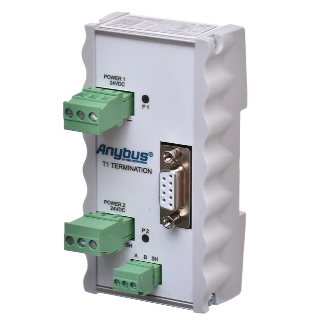
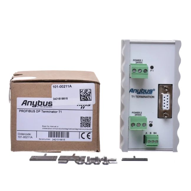


T1 Active PROFIBUS DP terminator

The T1 active terminator ensures proper termination of a PROFIBUS DP network segment. It also serves as a measurement point for connecting a PROFIBUS tester to the segment. More
Code: 101-00211A
The T1 active terminator ensures proper termination of a PROFIBUS DP network segment. It also serves as a measurement point for connecting a PROFIBUS tester to the segment. More
Code: 101-00211A
T1 · PROFIBUS DP RS485
Active terminator T1
Termination independent of the terminal station’s power supply
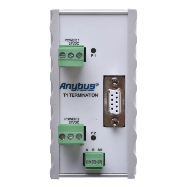
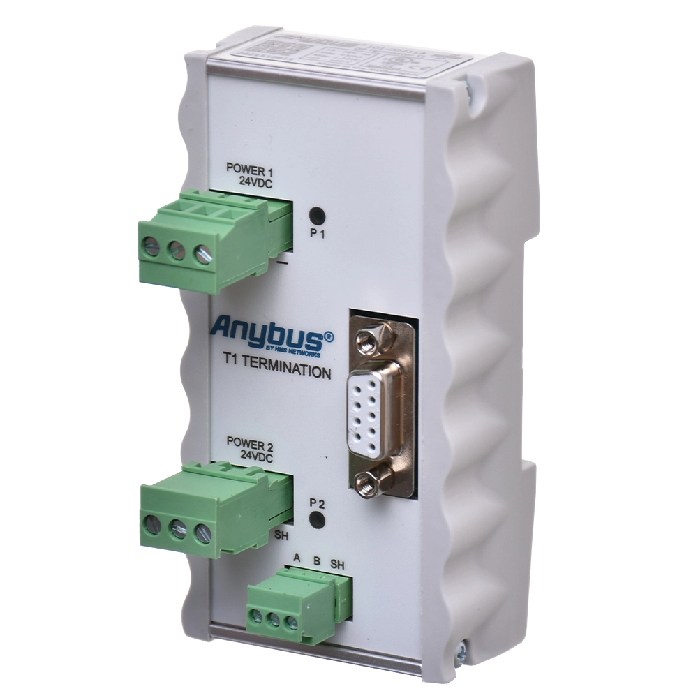
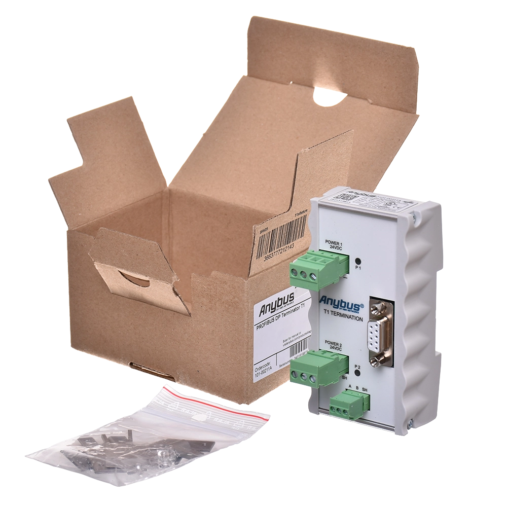
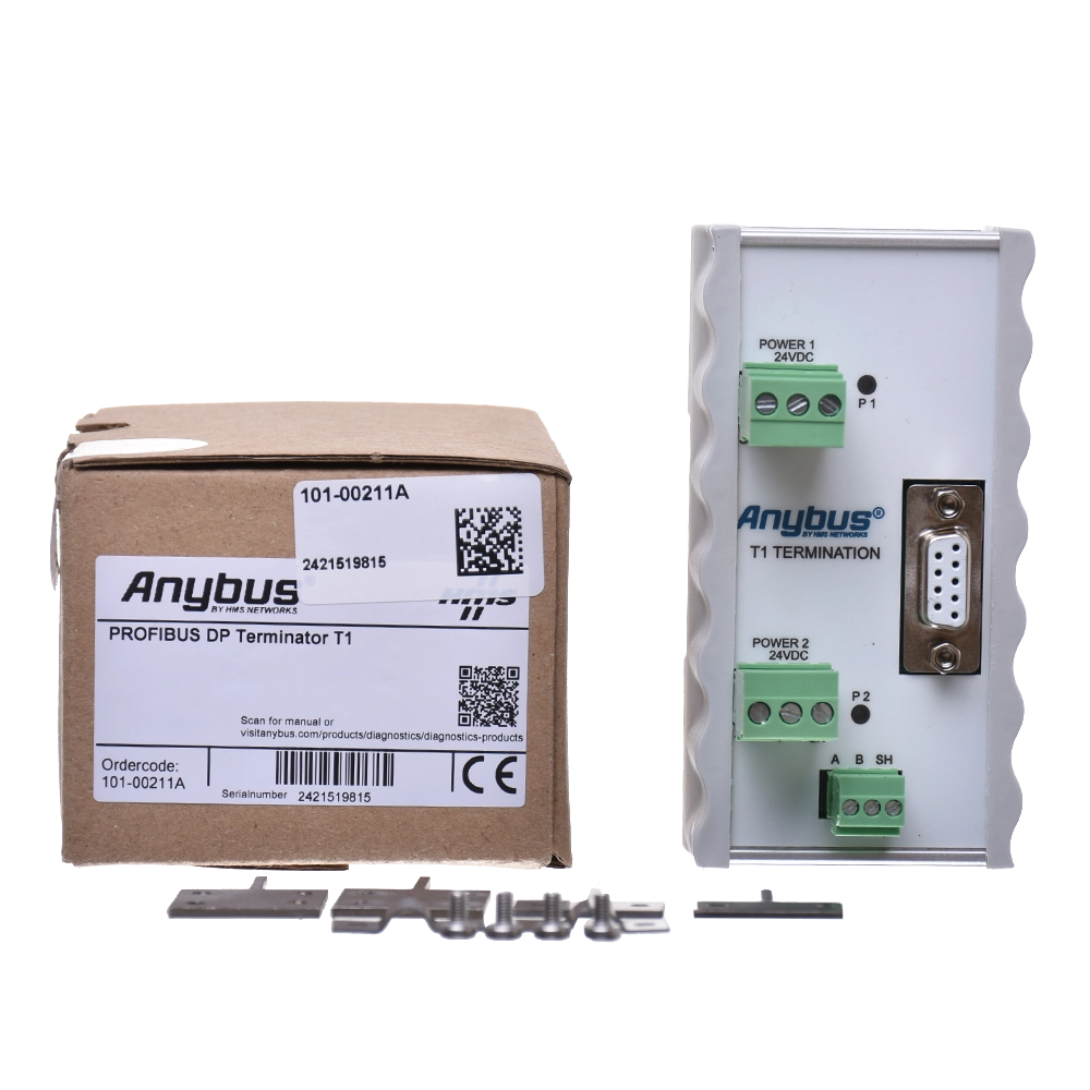
The T1 101-00211A provides an independently powered active termination for a PROFIBUS DP metallic segment. The termination is therefore not dependent on the power supply to the last station. Two power supply inputs allow for redundant power supply, whilst the DB9 connector provides an accessible measurement point for ProfiTrace or another analyser.
Send us the network topology and the power supply arrangements for the end stations. We will check the location of the T1 terminator and the required accessories.
Reliable termination during end-station maintenance
Termination built into the last peripheral often depends on its power supply. Switching that station off also removes its powered segment termination. T1 moves this function to a separate component with an independent power supply.
If connected correctly, this will minimise communication failures caused by a missing or unpowered terminator. The cable route between the other stations and the T1 must remain intact during maintenance.

Two segment ends, two correct terminations
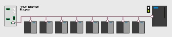
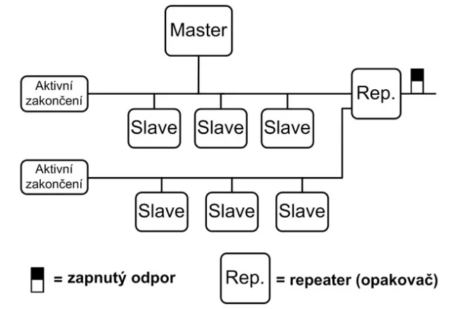
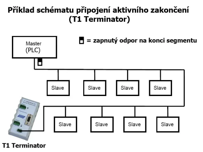
A segment is a section of the network in which the electrical signal is the same. Each metallic segment must be properly terminated at both ends with a termination resistor that is switched on and powered. The T1 forms the termination at one end of the segment; at the other end, there must be another correct, powered termination.
Place the T1 at the actual end of the segment. Do not connect another terminating resistor next to it at the same point. If you are using a DB9 connection, also check the position of the terminator in the connected PROFIBUS connector. Consider the termination of the entire route as a whole.
Two power inputs and status LEDs
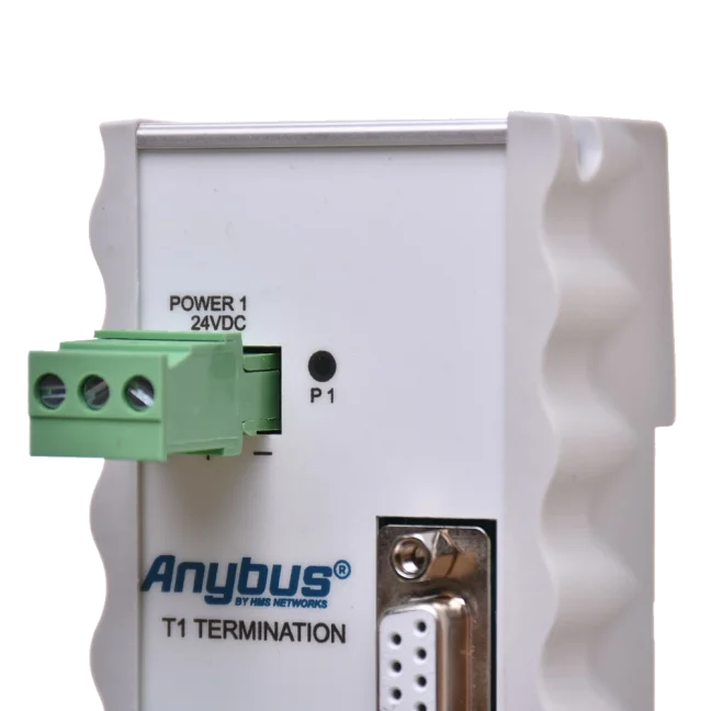
Supply the T1 with a DC voltage of 19 to 28 V DC. The current draw is 65 mA at 24 V DC. A single power input is sufficient for normal operation; true redundancy is provided by two independent power supplies. Should one power supply fail, the other will take over without delay.
Connect the power supply wires to the + and - terminals; use the SH terminal for earthing. Connecting two inputs to the same power supply does not replace two independent power supplies.
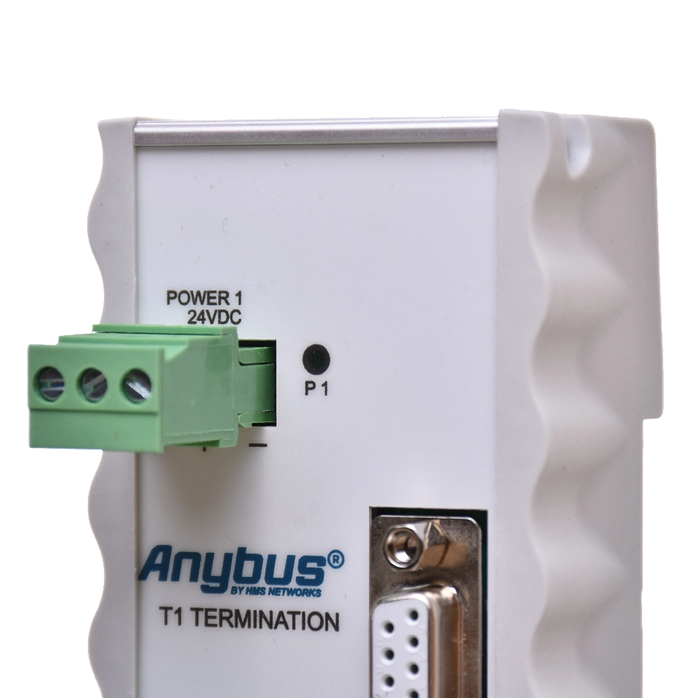
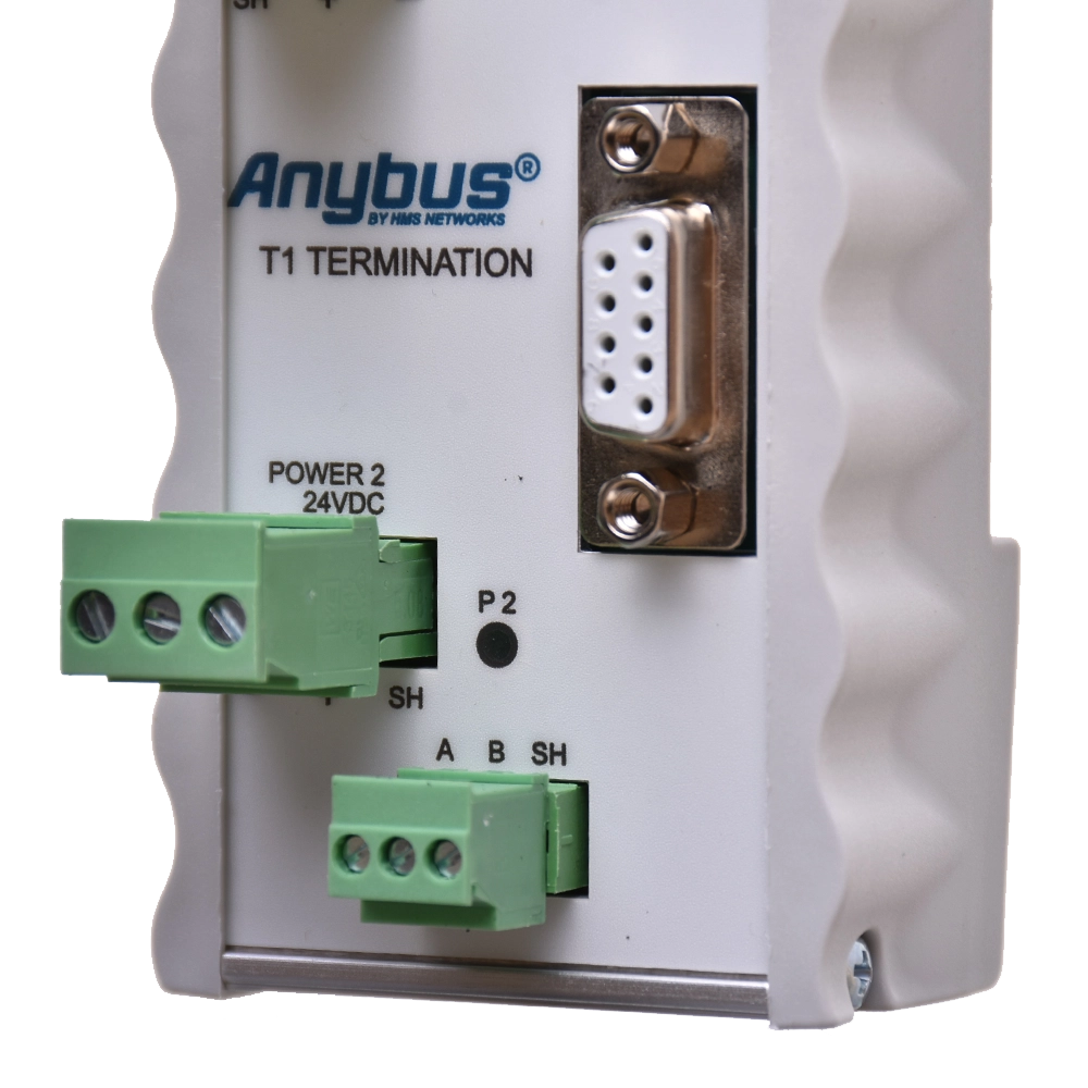
PROFIBUS terminal block and DB9 measurement point
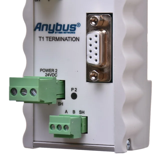
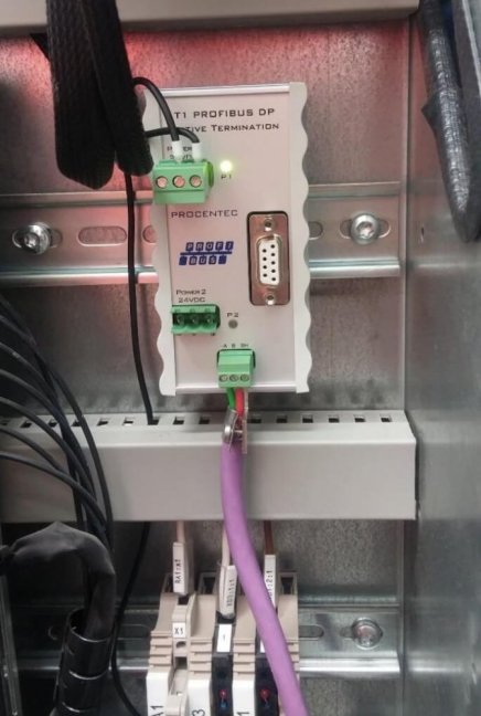
You would normally connect the PROFIBUS cable to the green terminal block: A is the green wire, B is the red wire and SH is the shield. The DB9 is electrically connected to the same bus. It does not create a new segment and does not provide galvanic isolation from the terminal block.
The DB9 can be used for signal measurement and communication diagnostics using a separate analyser. When you connect the cable to the terminal block, the DB9 remains free for maintenance. The T1 itself does not generate communication statistics; its LEDs indicate the status of the power inputs.
Connect the shield according to the bonding design. The GC-01 shield clip makes shield contact at the terminal block easier and provides cable strain relief.
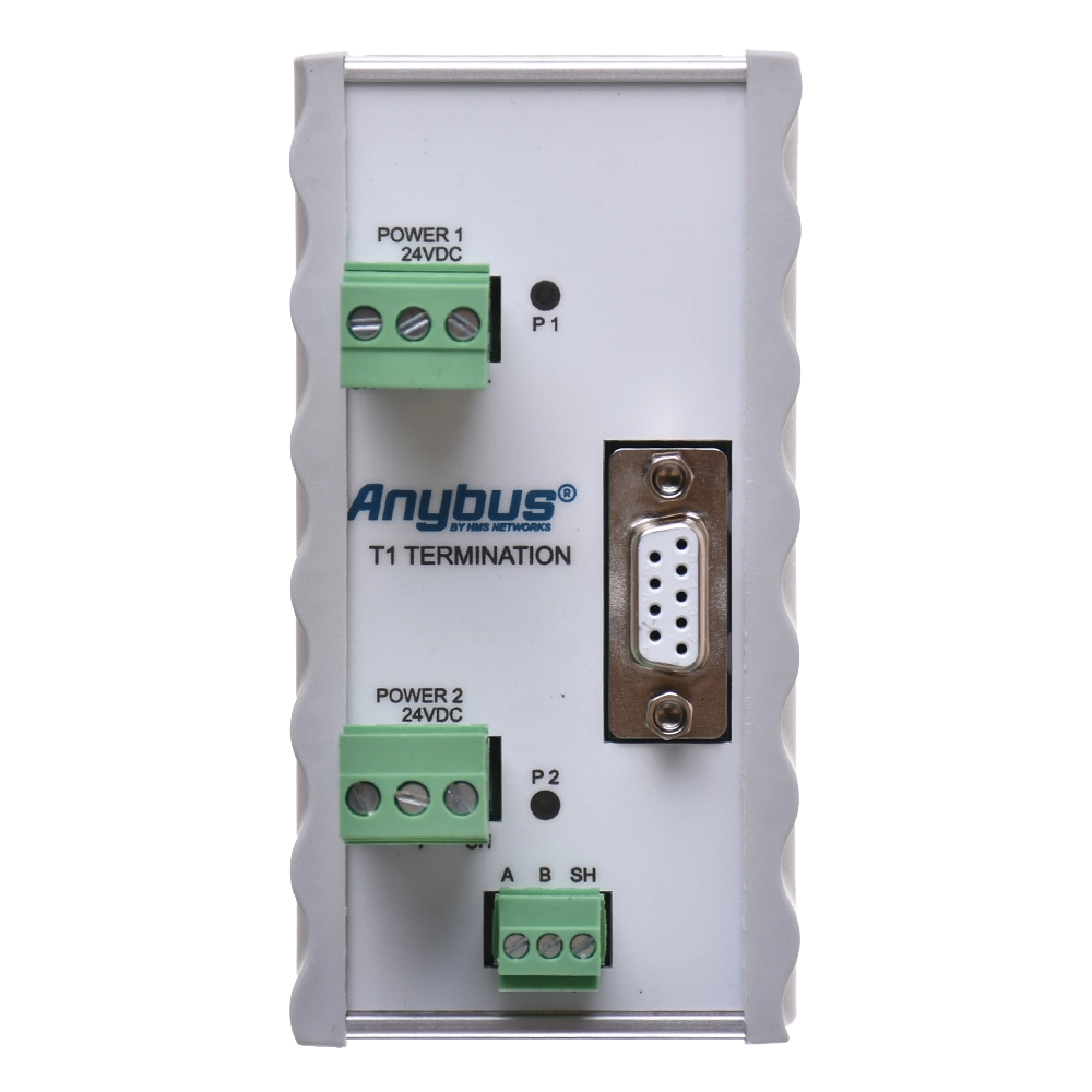
P1 and P2 power indicators
| The LED is lit continuously | The relevant power supply is working properly |
|---|---|
| The LED is flashing | Unstable power supply or internal fault; please also check the other input |
| The LED is not lit | No power supply or internal fault; please also check the other input |
LEDs P1 and P2 do not assess the quality of the telegrams or the PROFIBUS electrical signal. To carry out such a check, connect a separate analyser.
Shutting down peripheral devices and the PLC’s response
T1 does not require its own PROFIBUS address or entry in the PLC’s hardware configuration. However, the behaviour of the technology in the event of a power cut or loss of a peripheral is determined by the PLC’s configuration and programme. Maintaining the termination therefore does not in itself mean that production will continue after the station has been disconnected.
Before maintenance, check that unplugging the connector will not interrupt the through-wiring of other stations. Plan a safe procedure according to the role of the peripheral in the installation.
Cable length depending on the segment speed
T1 operates at speeds ranging from 9.6 kbit/s to 12 Mbit/s, including 45.45 kbit/s. It does not increase the permitted segment length; use a suitable repeater for the next segment.
| 9.6 / 19.2 / 45.45 / 93.75 kbit/s | 1200 m |
|---|---|
| 187.5 kbit/s | 1000 m |
| 500 kbit/s | 400 m |
| 1.5 Mbit/s | 200 m |
| 3 / 6 / 12 Mbit/s | 100 m |
The lengths stated apply to a correctly installed PROFIBUS DP RS485 cable. Termination alone will not rectify a damaged cable, a faulty connector or incorrect shielding.
Mounting on a DIN rail in a control cabinet
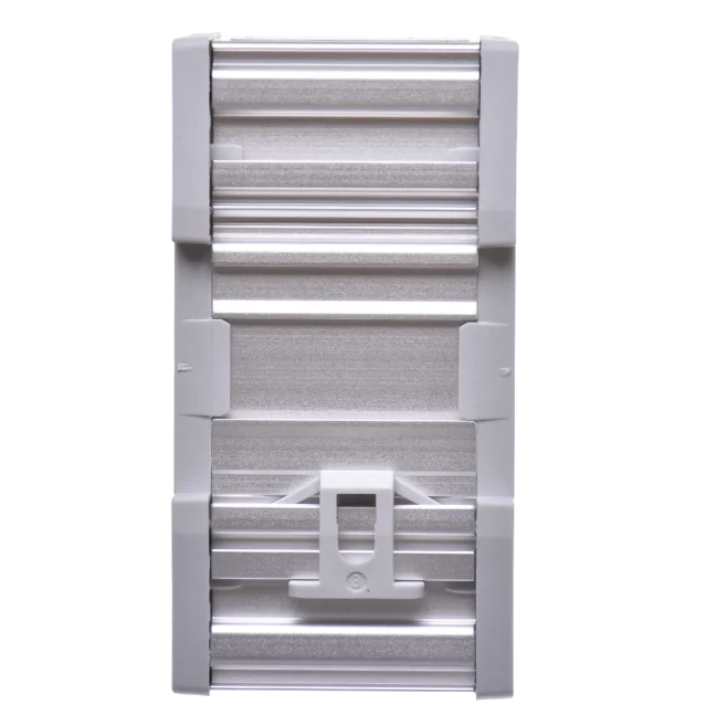
Mount the T1 on a standard 35 mm DIN rail. The recommended orientation is with the green PROFIBUS terminal block facing downwards; this makes it easier to read the LEDs and access the DB9 connector.
The protection rating is IP20, and the operating temperature range is -20 to +60 °C. When installing and handling the device, allow sufficient space for the connectors and for the cable to bend. The device is intended for use in a suitable, non-explosive environment.

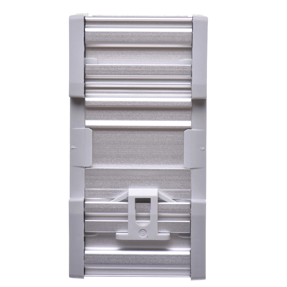
T1, order number 101-00211A
| Order number | 101-00211A |
|---|---|
| Uses | Active termination of one end of a PROFIBUS DP RS485 segment |
| Termination resistor network | 390 / 220 / 390 Ω, powered in accordance with IEC 61158 |
| Transfer rate | 9.6 kbit/s to 12 Mbit/s, including 45.45 kbit/s |
| Protocols | DP-V0 / DP-V1 / DP-V2, FDL, MPI, FMS, PROFIsafe and PROFIdrive; support at the physical layer does not replace an application safety assessment |
| Address and configuration | Without its own PROFIBUS address and without a GSD |
| Bus connection | A/B/SH terminal block or DB9 connector, electrically interconnected |
| PROFIBUS connection | A: green wire; B: red wire; SH: shielding |
| Power supply | 19-28 V DC |
| Power inputs | Two - one is enough for normal operation |
| Power connection | + positive supply, - 0 V, SH earth |
| Current consumption | 65 mA at 24 V DC |
| Reverse polarity protection | Yes |
| Signalling | P1 / P2: status of the relevant power supply input |
| Conductor cross-section | < 2.5 mm² |
| Protection rating | IP20 |
| Operating temperature | -20 to +60 °C |
| Installation | 35 mm DIN rail |
| Dimensions excluding plug-in connectors | 55 × 106 × 33 mm |
| Dimensions including connectors | 55 × 106 × 55 mm |
| Net catalogue weight | 120 g |
The weight stated is the net catalogue weight. We will confirm the specifications and full space requirements based on the specific delivery.
Module and accessories for connection
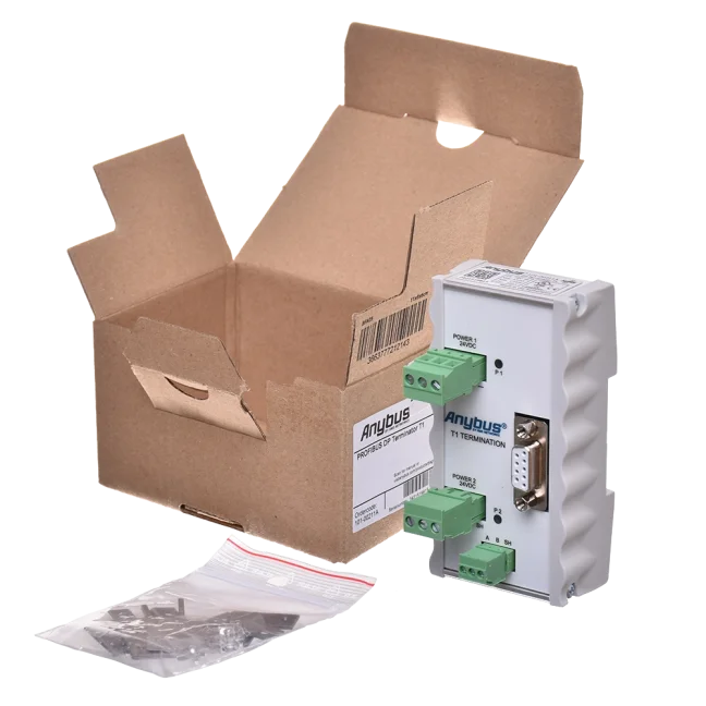
We will supply the T1 101-00211A active terminator. We will confirm the contents of the supplied connectors, shielding clamps and mounting parts in the quotation. We will select the power supply, PROFIBUS cable and analyser separately, depending on the specific installation.
Selection and connection of T1
When should the active T1 termination be used?
If the termination of the segment is to be independent of the power supply to the terminal station, connect T1 to the physical end of the segment and ensure it remains powered even during maintenance of the peripherals.
How many terminations does one segment need?
A segment is a section of the network in which the electrical signal is the same. Each metallic segment must be properly terminated at both ends with a termination resistor that is switched on and powered. The T1 forms the termination at one end of the segment; at the other end, there must be another correct, powered termination.
Is one T1 enough for the whole network?
A T1 terminates one end of a metallic segment. Each segment requires a powered termination at both ends. The number of T1s depends on the topology and on which terminations are already provided by other permanently powered components.
Will production continue after disconnecting the last PROFIBUS station?
T1 does not require its own PROFIBUS address or entry in the PLC’s hardware configuration. However, the behaviour of the technology in the event of a power cut or loss of a peripheral is determined by the PLC’s configuration and programme. Maintaining the termination therefore does not in itself mean that production will continue after the station has been disconnected.
Do I need a GSD or a change to the PLC programme?
The T1 does not have its own address and is not added to the project as a slave, so you do not need the GSD. Nevertheless, before disconnecting the peripheral, check the PLC’s response to its loss.
What sort of power supply do I need?
Supply the T1 with a DC voltage of 19 to 28 V DC. The current draw is 65 mA at 24 V DC. A single power input is sufficient for normal operation; true redundancy is provided by two independent power supplies. Should one power supply fail, the other will take over without delay.
Why order from FOXON
We have been an official distributor for HMS Anybus (formerly PROCENTEC) since 2007.
Segment termination design
We will review the physical cable ends, the end stations' power supplies and the location of the T1 terminator.
Selecting accessories
We will select the PROFIBUS cable, connectors, shielding clips and a suitable power supply.
Physical layer measurements
We can help you check reflections, signal levels and correct termination using an analyser.
Maintenance with termination preserved
We will check that cabling and powered termination remain in place when a peripheral is disconnected.
Czech technical support
We will discuss specific wiring configurations, fault symptoms and the control system’s response during maintenance.
Delivery in accordance with the project
Before placing an order, we will confirm the availability of the specific model, the quantity and the delivery date.
Manual and technical documentation
In the ‘Downloads’ tab, you will find the EN V1.3.2 installation manual, the latest HMS technical data sheet and the EU/UK declaration of conformity for T1 101-00211A.
Open downloadsTechnical specifications of the T1 active terminator
Order number 101-00211A. PROFIBUS DP RS485 active terminator for the end of a single segment.
Functions and communication
| Order number | 101-00211A |
|---|---|
| Uses | Active termination of one end of a PROFIBUS DP RS485 segment |
| Termination resistor network | 390 / 220 / 390 Ω, powered in accordance with IEC 61158 |
| Transfer rate | 9.6 kbit/s to 12 Mbit/s, including 45.45 kbit/s |
| Protocols | DP-V0 / DP-V1 / DP-V2, FDL, MPI, FMS, PROFIsafe and PROFIdrive; support at the physical layer does not replace an application safety assessment |
| Address and configuration | Without its own PROFIBUS address and without a GSD |
Connections and power supply
| Bus connection | A/B/SH terminal block or DB9 connector, electrically interconnected |
|---|---|
| PROFIBUS connection | A: green wire; B: red wire; SH: shielding |
| Power supply | 19-28 V DC |
| Power inputs | Two - one is enough for normal operation |
| Power connection | + positive supply, - 0 V, SH earth |
| Current consumption | 65 mA at 24 V DC |
| Reverse polarity protection | Yes |
| Signalling | P1 / P2: status of the relevant power supply input |
| Conductor cross-section | < 2.5 mm² |
Mechanical design
| Protection rating | IP20 |
|---|---|
| Operating temperature | -20 to +60 °C |
| Installation | 35 mm DIN rail |
| Dimensions excluding plug-in connectors | 55 × 106 × 33 mm |
| Dimensions including connectors | 55 × 106 × 55 mm |
| Net catalogue weight | 120 g |
Segment length as a function of speed
| 9.6 / 19.2 / 45.45 / 93.75 kbit/s | 1200 m |
|---|---|
| 187.5 kbit/s | 1000 m |
| 500 kbit/s | 400 m |
| 1.5 Mbit/s | 200 m |
| 3 / 6 / 12 Mbit/s | 100 m |
Correct termination and operation
A segment is a section of the network in which the electrical signal is the same. Each metallic segment must be properly terminated at both ends with a termination resistor that is switched on and powered. The T1 forms the termination at one end of the segment; at the other end, there must be another correct, powered termination.
Place the T1 at the actual end of the segment. Do not connect another terminating resistor next to it at the same point. If you are using a DB9 connection, also check the position of the terminator in the connected PROFIBUS connector. Consider the termination of the entire route as a whole.
T1 does not require its own PROFIBUS address or entry in the PLC’s hardware configuration. However, the behaviour of the technology in the event of a power cut or loss of a peripheral is determined by the PLC’s configuration and programme. Maintaining the termination therefore does not in itself mean that production will continue after the station has been disconnected.
Frequently asked questions about the T1 active terminator
Installation, power supply, maintenance and measurement of the segment.
Network Use and Design
When should the active T1 termination be used?
If the termination of the segment is to be independent of the power supply to the terminal station, connect T1 to the physical end of the segment and ensure it remains powered even during maintenance of the peripherals.
How many terminations does one segment need?
A segment is a section of the network in which the electrical signal is the same. Each metallic segment must be properly terminated at both ends with a termination resistor that is switched on and powered. The T1 forms the termination at one end of the segment; at the other end, there must be another correct, powered termination.
Is one T1 enough for the whole network?
A T1 terminates one end of a metallic segment. Each segment requires a powered termination at both ends. The number of T1s depends on the topology and on which terminations are already provided by other permanently powered components.
Will production continue after disconnecting the last PROFIBUS station?
T1 does not require its own PROFIBUS address or entry in the PLC’s hardware configuration. However, the behaviour of the technology in the event of a power cut or loss of a peripheral is determined by the PLC’s configuration and programme. Maintaining the termination therefore does not in itself mean that production will continue after the station has been disconnected.
Connections and Power Supply
Do I need a GSD or a change to the PLC programme?
The T1 does not have its own address and is not added to the project as a slave, so you do not need the GSD. Nevertheless, before disconnecting the peripheral, check the PLC’s response to its loss.
What sort of power supply do I need?
Supply the T1 with a DC voltage of 19 to 28 V DC. The current draw is 65 mA at 24 V DC. A single power input is sufficient for normal operation; true redundancy is provided by two independent power supplies. Should one power supply fail, the other will take over without delay.
Can I power both inputs from a single power supply?
Yes, but a single power supply does not provide redundancy. One input is sufficient for normal operation; for true redundancy, use two independent power supplies within the range of 19 to 28 V DC.
Is DB9 a separate segment?
You would normally connect the PROFIBUS cable to the green terminal block: A is the green wire, B is the red wire and SH is the shield. The DB9 is electrically connected to the same bus. It does not create a new segment and does not provide galvanic isolation from the terminal block.
Diagnostics and operation
What do the P1 and P2 LEDs indicate?
Each LED corresponds to one power input. A steady light indicates that the power supply is working correctly; a flashing light indicates an unstable power supply or an internal fault. A dark LED indicates a lack of power or a fault; please also check the other input.
Will T1 increase the permitted cable length?
No. The T1 marks the end of the current segment. To extend the route and create another electrical segment, select a suitable repeater or ProfiHub. The maximum length of each segment is determined by the transmission speed.
Can the termination also be switched on in the connector next to T1?
Place the T1 at the actual end of the segment. Do not connect another terminating resistor next to it at the same point. If you are using a DB9 connection, also check the position of the terminator in the connected PROFIBUS connector. Consider the termination of the entire route as a whole.
Can the network be monitored via T1 using ProfiTrace?
The DB9 can be used for signal measurement and communication diagnostics using a separate analyser. When you connect the cable to the terminal block, the DB9 remains free for maintenance. The T1 itself does not generate communication statistics; its LEDs indicate the status of the power inputs.

PROFIBUS: 3 Sins and 10 Tips
The PROFIBUS industrial bus is highly tolerant and will forgive many faults. But if a critical fault occurs—or several small ones accumulate—you will definitely notice. That’s why this aging industrial network deserves attention. Even if faults on your network are still rare, they will gradually accumulate. What do our technicians recommend? What are their 10 tips for maintaining PROFIBUS?
We train the basics and troubleshooting of PROFIBUS networks | FOXON Academy
Do you want to know why your industrial communication is dropping out? Know where the errors are on the bus and fix them quickly? How the PROFIBUS network works and how to upgrade it and make it more robust? Learn all this in a training session full of practical examples
Highlighted items are mandatory.

Training PROFIBUS - Basics, Diagnostics & Network Troubleshooting, 2 days
1 076,90 EUR Incl. VAT

Diagnostics, troubleshooting and monitoring of PROFIBUS networks
from 367,84 EUR Incl. VAT

PROFIBUS Connector without PG Port, cable outlet direct 180°
26,62 EUR Incl. VAT

PROFIBUS Connector with PG Port, cable outlet in 35° or 90°
30,25 EUR Incl. VAT

LAPP 2170222 - PROFIBUS DP trailing cable
4,84 EUR Incl. VAT

ProfiTrace 2 Ultra Plus – PROFIBUS DP Tester
4 399,56 EUR Incl. VAT
ProfiHub B5+R PROFIBUS multi-repeater
1 724,25 EUR Incl. VAT
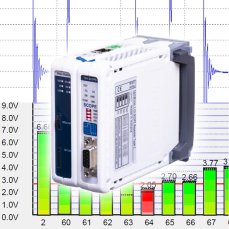
ComBricks Standard set for permanent monitoring of one PROFIBUS network / segment
3 037,10 EUR Incl. VAT
Related products8
Training PROFIBUS - Basics, Diagnostics & Network Troubleshooting, 2 days
1 076,90 EUR Incl. VAT
Diagnostics, troubleshooting and monitoring of PROFIBUS networks
from 367,84 EUR Incl. VAT
PROFIBUS Connector without PG Port, cable outlet direct 180°
26,62 EUR Incl. VAT
PROFIBUS Connector with PG Port, cable outlet in 35° or 90°
30,25 EUR Incl. VAT
LAPP 2170222 - PROFIBUS DP trailing cable
4,84 EUR Incl. VAT
ProfiTrace 2 Ultra Plus – PROFIBUS DP Tester
4 399,56 EUR Incl. VAT
ProfiHub B5+R PROFIBUS multi-repeater
1 724,25 EUR Incl. VAT
ComBricks Standard set for permanent monitoring of one PROFIBUS network / segment
3 037,10 EUR Incl. VAT