

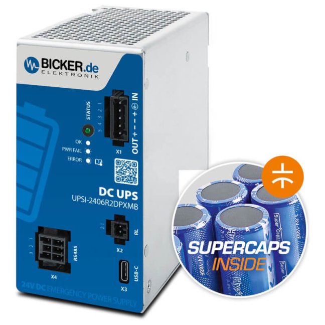


144 W 24 VDC / 6 A UPS backup power supply Bicker with supercapacitor and USB-C + RS485 Modbus interfaces

Smart industrial DC UPS backup power supply 24 VDC / 6 A, 144 W with integrated supercapacitor, configuration via UPScom software, USB-C and RS485 Modbus interfaces, DIN rail mounting More
Code: UPSI-2406R2DP2MB
Smart industrial DC UPS backup power supply 24 VDC / 6 A, 144 W with integrated supercapacitor, configuration via UPScom software, USB-C and RS485 Modbus interfaces, DIN rail mounting More
Code: UPSI-2406R2DP2MB
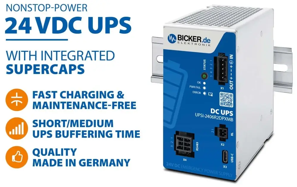
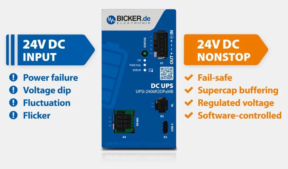
Modern and reliable protection against short-term power outages using supercapacitors – with fast charging and USB-C / RS485 Modbus interfaces
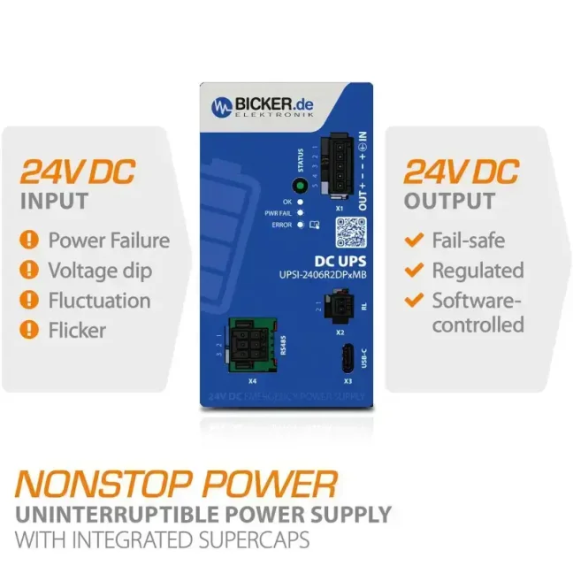
Are you dealing with short-term power outages or voltage drops in control cabinets? Avoid costly downtime and data loss. The industrial DC UPS UPSI-2406R2DP2MB with integrated supercapacitor-based energy storage reliably bridges short-term outages, voltage dips, and power fluctuations, thus ensuring an uninterrupted 24 VDC power supply at the output. UPS status and control are available in two ways: from a PC via USB-C and UPScom software, or directly from a PLC/SCADA via RS485 Modbus.
Main features and benefits for industrial applications:
- Stable power supply: ensures uninterrupted 24 VDC power with a load of up to 6 A (144 W) even in the event of a mains failure.
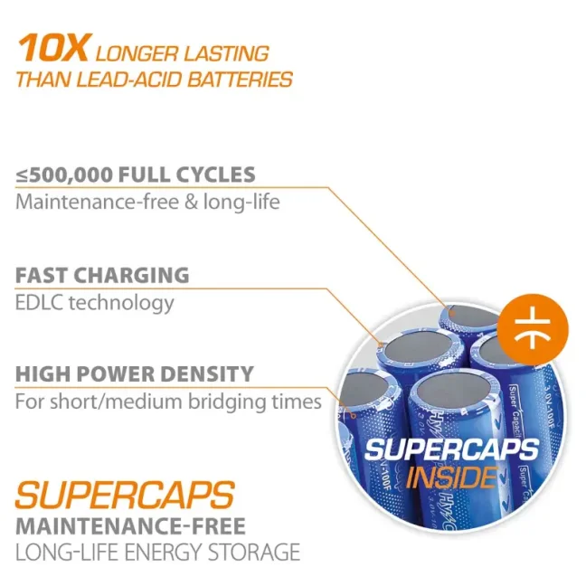
- Extremely long service life: supercapacitors withstand up to 500,000 charge and discharge cycles.
- Maintenance-free operation thanks to supercapacitors.
- Smart power management functions:
- Power Sharing: intelligently distributes input power between the connected load and the supercapacitors. There is no need to oversize the AC/DC power supply.
- Controlled shutdown and restart (UPScom): in the event of a power failure, it enables safe shutdown of connected devices and their automatic restart once power is restored.
- Configurable parameters: UPS behavior can be configured (e.g. load sensor, shutdown delay, maximum backup time) via UPScom software.
- Minimum load detection: automatic shutdown at low or no load to save energy.
- Power-fail timer function: definable behavior during a power failure according to a configured time scenario.
- Switching time: transition from normal to backup mode < 3 ms.
- Advanced management and diagnostics for programmers and maintenance personnel:
- UPScom software (free download): enables comprehensive configuration and real-time monitoring of the DC UPS system.
- Controlled shutdown and restart: in the event of a power failure, the software ensures controlled shutdown of connected devices (e.g. an industrial PC) to save data and prevent damage. Once power is restored, it automatically restarts the system without requiring manual intervention.
- Script support: custom scripts (batch files) can be executed before system shutdown for application-specific processes.
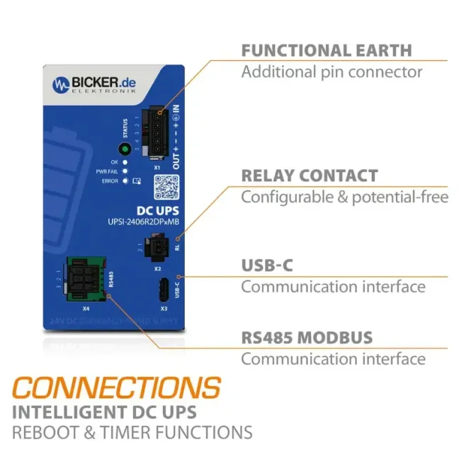
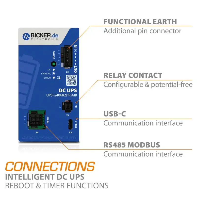
- Communication: USB-C and RS485 Modbus interfaces for configuration, management, and collection of status data.
- E-mail notifications: automatic alerts in the event of loss of connection with the UPS, system shutdown, or power failure. These preventive measures help reduce or completely eliminate downtime.
- Configurable parameters: load sensor, shutdown delay, maximum backup time, minimum charge capacity, and more.
- Plug & Play: the device is recognized by the operating system as a UPS.
- UPScom software (free download): enables comprehensive configuration and real-time monitoring of the DC UPS system.
- Easy installation and durable design:
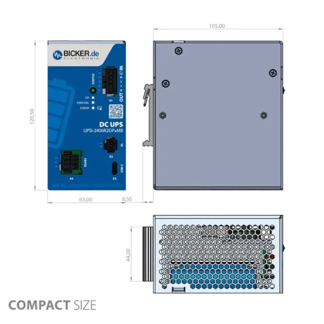
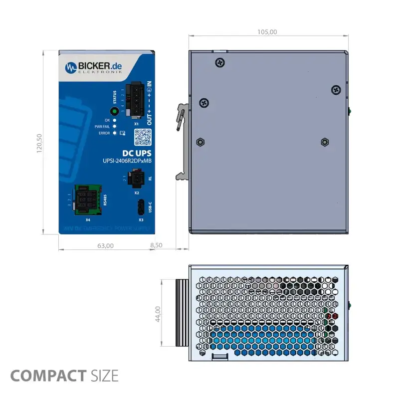
- Compact design for DIN rail mounting, ideal for control cabinets and decentralized solutions.
- Operating temperature: from -20 °C to +65 °C.
- Enhanced robustness and safety (EMC, protection features, operational reliability):
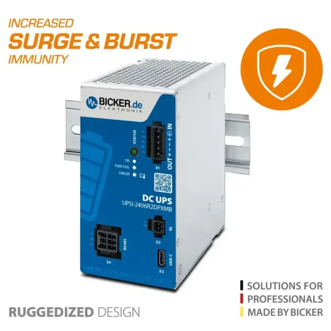
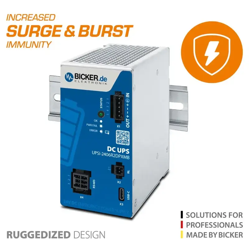
- Resistance to interference and surge peaks (EMC):
- EN 61000-4-4 (Burst): test voltage up to 2 kV, criterion A
- EN 61000-4-5 (Surge): ±0.5 kV (L–N) and ±1 kV (L–PE, N–PE), criterion A
- Protection functions:
- Protection against reverse polarity at the input, overcurrent, and short circuit at the output
- Integrated control and monitoring of the energy storage system for safe operation
- Practical impact: suitable for use in industrial control cabinets and applications with higher electromagnetic stress (load switching, interference, surge peaks on the 24 V branch)
- Resistance to interference and surge peaks (EMC):
- Advanced management and diagnostics for programmers and maintenance personnel:
- UPScom software (free download): enables comprehensive configuration and real-time monitoring of the DC UPS system.
- Controlled shutdown and restart: in the event of a power failure, the software ensures controlled shutdown of connected devices (e.g. an industrial PC) to save data and prevent damage. Once power is restored, it automatically restarts the system without requiring manual intervention.
- Script support: custom scripts (batch files) can be executed before system shutdown for application-specific processes.
- Communication: USB-C (HID UPS, Plug&Play) for configuration and management (UPScom), and RS485 Modbus for transmitting status data to a PLC or SCADA system.
- E-mail notifications: automatic alerts in the event of loss of connection with the UPS, system shutdown, or power failure (UPScom software function).
- Configurable parameters: load sensor, shutdown delay, maximum backup time, minimum charge capacity, and more.
- UPScom software (free download): enables comprehensive configuration and real-time monitoring of the DC UPS system.
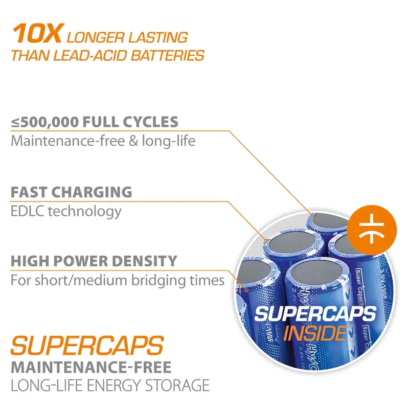
Long service life of supercapacitors – maintenance-free energy storage
Completely maintenance-free supercapacitors are available for uninterruptible DC power supplies, serving as highly efficient and exceptionally durable energy storage with a service life of up to 500,000 charge and discharge cycles for short-term and medium-term bridging times.
Unlike batteries, which store energy through a chemical reaction, supercapacitors operate on an electro-physical principle and can be charged and ready for use within a very short time. Under comparable operating conditions, supercapacitors have up to a ten times longer service life than conventional lead-acid batteries.
Supercapacitor-based storage systems also excel in high current capability, power density, and reliability. The long-life supercapacitor energy storage system operates over an extended temperature range and is equipped with integrated cell balancing.
.
Main advantages of supercapacitors compared to lead-acid and LiFePO₄ batteries
🔋 1. Service life and cycles
- Supercapacitors: up to 500,000 charge and discharge cycles, with virtually no wear.
- Lead-acid batteries: approx. 500–1,000 cycles, degrade quickly.
- LiFePO₄: approx. 3,000–7,000 cycles, much better than lead-acid, but still significantly less than supercapacitors.
⚡ 2. Charging and discharging speed
- Supercapacitors: charge within seconds to minutes, immediately ready for use.
- Lead-acid batteries: charging takes hours.
- LiFePO₄: faster than lead-acid, but still requires tens of minutes to hours.
🌡 3. Temperature resistance
- Supercapacitors: operate over a wide range of -20 to +65 °C (sometimes more).
- Lead-acid batteries: issues already appear around 0 °C and above 40 °C.
- LiFePO₄: better than lead-acid, but charging below 0 °C is problematic.
🛠 4. Maintenance and reliability
- Supercapacitors: completely maintenance-free, contain no liquid electrolyte.
- Lead-acid batteries: may require maintenance (checking electrolyte level) and also degrade due to sulfation.
- LiFePO₄: maintenance-free, but require a BMS (Battery Management System) for cell protection.
⚙️ 5. Performance and load capability
- Supercapacitors: very high current capability, ideal for short-term outages and peak loads.
- Lead-acid batteries: lower current capability, discharge quickly under heavy load.
- LiFePO₄: better than lead-acid, but still not as exceptionally robust as supercapacitors.
❗ Disadvantages of supercapacitors (compared to batteries)
- Lower energy density → they cannot store as much energy (unsuitable for long backup times measured in hours).
- Higher cost per Wh than both lead-acid and LiFePO₄.
- They are typically used for short-term bridging of outages (seconds to minutes), not for long-term power supply.
👉 Summary:
- Supercapacitors = extreme service life, fast charging, high reliability, but small “energy reservoirs”.
- LiFePO₄ = the best compromise for longer backup time, with longer service life than lead-acid.
- Lead-acid batteries = inexpensive, but heavy, with short service life and low efficiency.
Power Sharing with intelligent input current detection
Thanks to the intelligent Power Sharing function, there is no need to oversize the input AC/DC power supply. The input power is kept constant and intelligently distributed between supplying the load and charging the supercapacitor storage. At low output load, more energy is directed to the charger; conversely, at higher load, more power is delivered directly to the load. This saves both energy and costs.
Minimum load detection
Thanks to the integrated load sensor, the DC UPS switches off automatically as soon as the load value falls below the set threshold (no-load condition). This prevents unnecessary energy consumption.
Configuration via UPScom software
The UPScom software (free to download) allows controlled shutdown and disconnection of connected devices in the event of a power failure to prevent data loss or damage. The responsive web user interface (WEB UI) opens in a web browser and is used to set and preprogram all parameters of the DC UPS system, as well as for real-time monitoring with a UPS charge status indicator. Adjustable parameters include, among others, load sensor (mA), shutdown delay, maximum backup time, minimum charge capacity before system startup, and e-mail alerts.
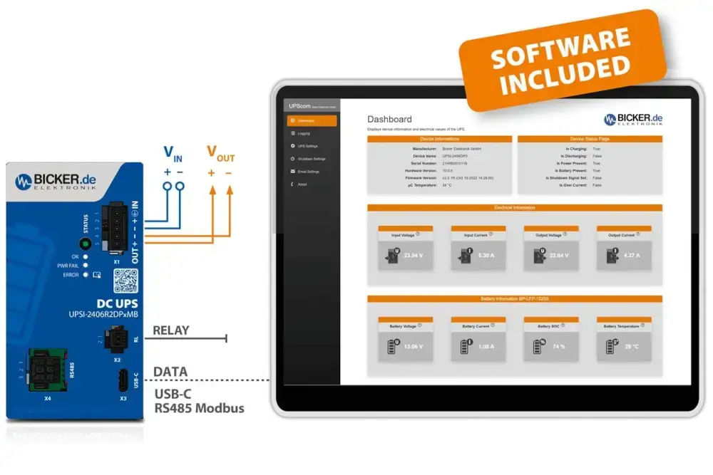
Secure shutdown and restart function for IPC systems
In the event of a power failure, the UPS signals voltage loss via the integrated interfaces so that a controlled shutdown of the computer system can be initiated and valuable data can be saved. Before the system shuts down, a custom script (batch file) can also be started to perform application-specific processes. The integrated restart function of the DC UPS automatically restarts the powered IPC once the voltage is restored, without the need for lengthy on-site intervention by a service technician – for example in fully autonomous computer systems located in inaccessible places.
E-mail notification service
UPScom sends you an e-mail in the event of loss of communication with the UPS, system shutdown, or power failure. These preventive measures can reduce or completely eliminate downtime.

UPS configuration via USB
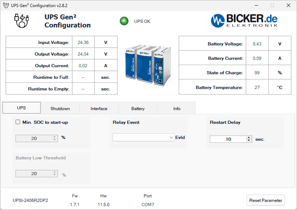
Connect the UPSI-2406R2DP2MB to your computer using a USB cable. In UPS Gen² Configuration, you can configure UPS behaviour and view its operating data. The screenshots below show the individual program tabs.
The UPSI-2406R2DP2MB stores energy in EDLC supercapacitors. Battery labels in the program refer to this energy storage device, not to a Li-Ion battery. Click an image to open it separately for a detailed view. The values shown are examples of a specific configuration and operating state.
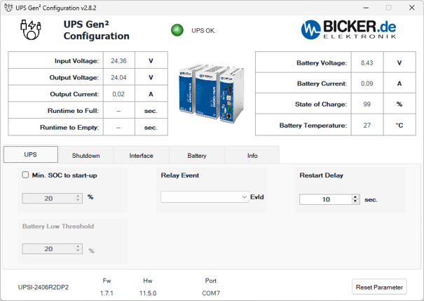
The power and energy storage overview at the top and the identification bar at the bottom appear in all five screenshots. These are read-only data; settings are changed in the individual tabs.
Common information on all screens
- Input Voltage [V]
- UPS input voltage. This value is available during normal operation from the upstream power supply.
- Output Voltage [V]
- Voltage at the UPS output supplying the connected equipment. It is displayed during both normal and backup operation.
- Output Current [A]
- Current drawn by the equipment connected to the UPS output.
- Runtime to Full [sec.]
- Estimated time until the supercapacitor energy storage device is fully charged. These screenshots show the time in seconds, not minutes.
- Runtime to Empty [sec.]
- Estimated remaining backup time under the current load, shown here in seconds. This is not a guaranteed operating time. Dashes mean that the program is not currently displaying an estimate.
- Battery Voltage [V]
- Current voltage of the supercapacitor energy storage device. It is not the same as the UPS output voltage.
- Battery Current [A]
- Energy storage current. A positive value indicates charging; a negative value indicates discharging.
- State of Charge [%]
- Current state of charge of the supercapacitor energy storage device, abbreviated SOC. The percentage thresholds for startup and shutdown use this value.
- Battery Temperature [°C]
- Temperature reported for the energy storage device. For the DP2, this relates to the supercapacitor module, not the UPS processor temperature.
- Status indicator and UPS OK.
- Indication of the current UPS operating state. The example shows a green indicator and the message UPS OK.
- Program name and version
- The title bar shows the configuration program name and version. The screenshots show UPS Gen² Configuration v2.8.2.
- UPS / Shutdown / Interface / Battery / Info
- Tabs for UPS settings, shutdown conditions, communication interfaces, energy storage data and device identification. The operating data overview at the top remains the same on all five screens.
- Device identification
- Model reported by the connected UPS. The screenshots show UPSI-2406R2DP2. The full order designation of this product is UPSI-2406R2DP2MB; the MB suffix identifies the RS485 Modbus variant.
- Fw
- Version of the firmware installed in the UPS. The screenshots show 1.7.1. This is different from the version of the program on the computer.
- Hw
- UPS hardware version. The screenshots show 11.5.0.
- Port
- Port used for the USB-C connection between the program and the UPS, here COM7. This is a virtual serial port on the computer, not a device address on the Modbus network.
- Save Parameter
- Function for saving modified parameters to the UPS. The configuration program can be closed after saving. The Save Parameter button is not shown in these screenshots.
- Reset Parameter
- Restores the default parameter values. This is not the button for saving settings normally.
UPS tab settings
- Min. SOC to start-up [%]
- Minimum energy storage charge required to enable the UPS output. After being switched on or restarted, the UPS waits until the supercapacitors reach the set charge level before allowing power to the load. The screenshot shows 20 %, but the option is not checked.
- Battery Low Threshold [%]
- Low energy storage charge threshold for relay signalling. The screenshot shows 20 % and the field is inactive. This threshold is used for charge signalling; it is separate from the command to shut down the operating system.
- Restart Delay [sec.]
- Time for which the output remains off during a restart sequence before being switched on again. It provides a defined off period during which capacitances in the connected equipment can discharge. The screenshot shows 10 seconds. Automatic computer startup also requires the appropriate BIOS settings.
- Relay Event / EvId
- Field for selecting the relay contact event. EvId denotes the event identifier. The menu is not expanded in the screenshot, and the field does not show a selected event. Available events and contact logic must be verified for the specific R2 firmware.
Relay settings depend on the supported UPS hardware and firmware version. Before connecting the relay to a machine control system, we will help verify the required event and the resulting contact logic.
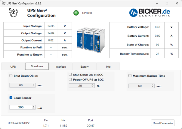
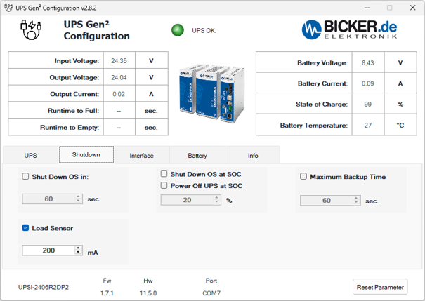
The upper section again displays power supply data, load current, energy storage charge and temperature; the bottom bar identifies the UPS, firmware, hardware and communication port. The Shutdown tab determines when computer shutdown begins or the UPS output is disconnected.
- Shut Down OS in [sec.]
- Time from the start of backup operation until the command to shut down the operating system is sent. If input power returns sooner, the timed shutdown condition does not take effect. The screenshot shows 60 seconds, but the option is not checked.
- Load Sensor [mA]
- Low load detection. If the load current falls below the set limit during backup operation, the UPS switches off its output and disconnects the energy storage device to limit discharge. In the screenshot, the function is enabled with a threshold of 200 mA.
- Shut Down OS at SOC [%]
- Initiates operating system shutdown when charge falls below the set threshold while the UPS is still running on supercapacitor power. The screenshot shows 20 %, but the option is not enabled.
- Power Off UPS at SOC
- Option for switching off the UPS according to its state of charge. It is separate from the Shut Down OS at SOC command. Its exact threshold and interaction with operating system shutdown must be confirmed for the firmware used; the option is not enabled in the screenshot.
- Maximum Backup Time [sec.]
- Maximum permitted backup operating time. When the configured limit expires, the UPS disconnects power to the load. The screenshot shows 60 seconds, but the function is not enabled. The limit does not guarantee that the stored energy will last that long. For a computer, allow enough time for the operating system to shut down completely before disconnecting the output.
- Checkboxes
- Enable or disable the corresponding condition. A number shown in an unchecked field does not by itself mean that the function is active.
Using time and charge thresholds together: if both Shut Down OS in and Shut Down OS at SOC are enabled, whichever condition occurs first triggers shutdown.
Windows settings: for shutdown via USB HID, set the power button action to Shut down. Disable automatic sleep while powered by the UPS; otherwise its low current draw could activate Load Sensor.
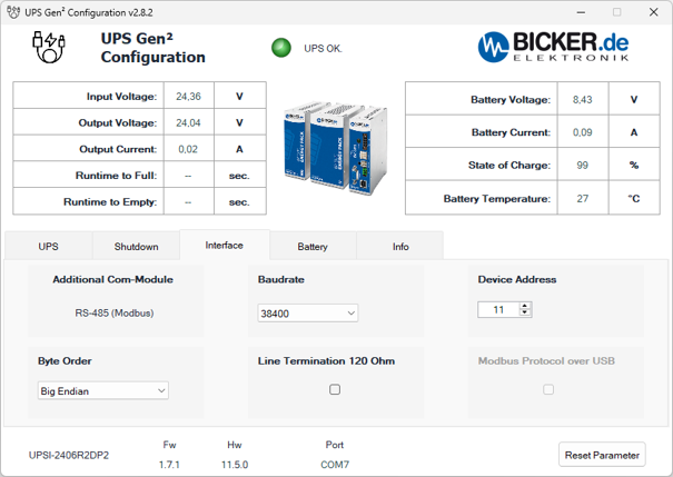
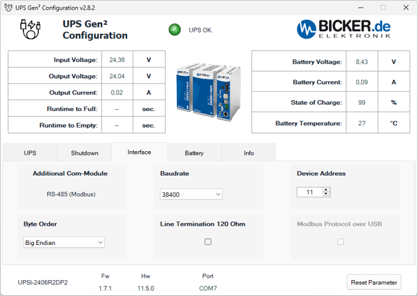
In addition to USB-C, the UPSI-2406R2DP2MB has an RS485 interface with Modbus RTU. The configuration program connects via USB; this tab configures communication with a PLC or another Modbus client. The values in the screenshot are examples, not universal settings for every network.
- Additional Com-Module
- Type of additional communication interface. The screenshot shows RS-485 (Modbus), matching the MB variant of this product.
- RS-485 (Modbus)
- Serial link for Modbus RTU communication, for example with a PLC or SCADA system. This is neither an RS232 interface nor Modbus TCP over Ethernet.
- Baudrate
- RS485 line transmission rate. The screenshot shows 38400 baud. The rate must match the settings of the other devices on the same line.
- Device Address
- Device address on the Modbus network. The screenshot shows 11. The client must use the same address, and individual devices on the line must have different addresses. This is not the USB port number COM7.
- Byte Order
- Byte order used when transferring data. The screenshot shows Big Endian, meaning the most significant byte is sent first. The setting must match how the client processes data; this option alone does not define the register map or the order of multiple registers within a value.
- Line Termination 120 Ohm
- Option for terminating the RS485 line with a 120 Ω resistor. It is unchecked in the screenshot. Termination is used at both ends of the main line, not automatically at every device; it depends on the actual bus wiring.
- Modbus Protocol over USB
- Option for selecting Modbus communication over USB. It is inactive and unchecked in the screenshot. This example does not confirm that the mode is available for the firmware used; support must be verified before use.
- Port COM7
- Virtual serial port used for the USB-C connection between the configuration program and the UPS. It is independent of the Modbus device address and is not a device number on the RS485 line.
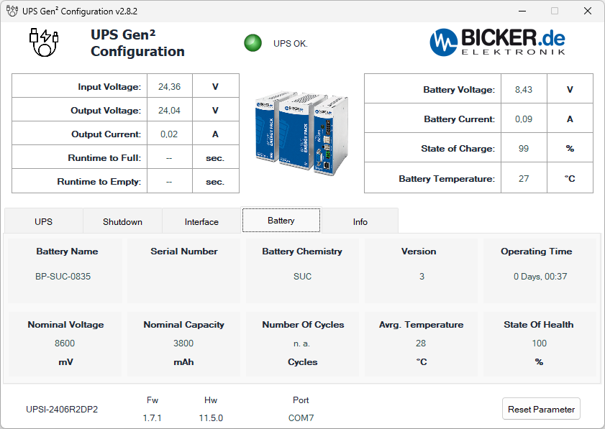
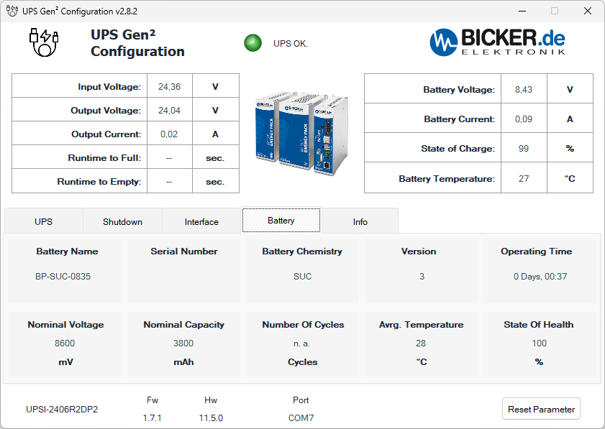
The Battery tab displays identification and operating data for the supercapacitor energy storage device. It is not a form for changing the storage type or capacity. The upper overview continues to show its instantaneous voltage, current, charge and temperature.
- Battery Name
- Designation of the connected energy storage device. The example shows BP-SUC-0835, the supercapacitor module used in the UPSI-2406R2DP2MB.
- Serial Number
- Serial number reported by the energy storage device. The field is blank in the screenshot. This is different from the UPS serial number on the Info tab.
- Battery Chemistry
- Energy storage technology. SUC in the example denotes supercapacitors, or EDLC. It does not designate a Li-Ion battery.
- Version
- Version reported by the energy storage module, here 3. This is neither the configuration program version nor the firmware version of the entire UPS.
- Operating Time
- Displayed operating time counter in days, hours and minutes; the example shows 0 Days, 00:37. This value alone does not establish the energy storage device's manufacturing date or age.
- Nominal Voltage [mV]
- Nominal voltage reported by the energy storage module in millivolts. It is separate from both the instantaneous Battery Voltage shown in the upper overview and the UPS output voltage.
- Nominal Capacity [mAh]
- Field for capacity reported by the module; the program uses mAh on this screen as well. The DP2 uses supercapacitors, so do not interpret this value as the capacity of a Li-Ion battery. When designing a backup system, use the storage device's nominal and usable energy in kJ or Wh and the backup time under the relevant load.
- Number of Cycles [Cycles]
- The SUC energy storage device does not provide the full charge and discharge cycle count here. The screenshot shows n. a.; this does not mean zero cycles or indicate the supercapacitors' remaining service life.
- Avg. Temperature [°C]
- Average temperature reported in the energy storage overview. It is different from the instantaneous Battery Temperature at the top of the window.
- State of Health [%]
- Energy storage health indicator, abbreviated SOH. Do not confuse it with SOC, the current state of charge. SOH support must be confirmed for the specific supercapacitor module and firmware; a displayed value of 100 % alone does not confirm measured usable energy or remaining service life.
The values in the screenshot relate to one specific connected setup. When designing a backup system, use the specifications of the supplied UPSI-2406R2DP2MB and its supercapacitor energy storage device rather than the figures in this program example.
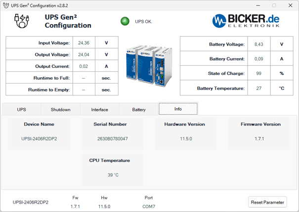
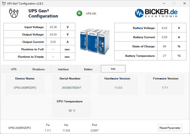
This tab summarises the information needed for device identification, version checks and technical support. The upper section displays the same power supply and energy storage operating data as the previous screens.
- Device Name
- Model reported by the UPS in the program, here UPSI-2406R2DP2. The order designation of this product is UPSI-2406R2DP2MB, the variant with an RS485 Modbus interface.
- Serial Number
- Serial number of the UPS itself, used to identify the individual unit for technical support or servicing.
- Hardware Version
- UPS hardware version, here 11.5.0. The same value appears as Hw in the bottom bar.
- Firmware Version
- UPS internal firmware version, here 1.7.1. The same value appears as Fw in the bottom bar. This is not the version of the configuration program on the computer. Any update must be selected for the exact UPS model and hardware version.
- CPU Temperature [°C]
- Temperature of the processor in the UPS control electronics. This is neither the supercapacitor energy storage temperature nor the temperature of the connected computer.
- Bottom bar and Reset Parameter
- The model, Fw, Hw and Port repeat the identification and connection information. Reset Parameter restores the default UPS parameters; its meaning remains the same when switching tabs.
Technical parameters
Basic features
- Device type: intelligent DC UPS module for 24 V systems
- Input voltage: 24 VDC (range 23–30 V)
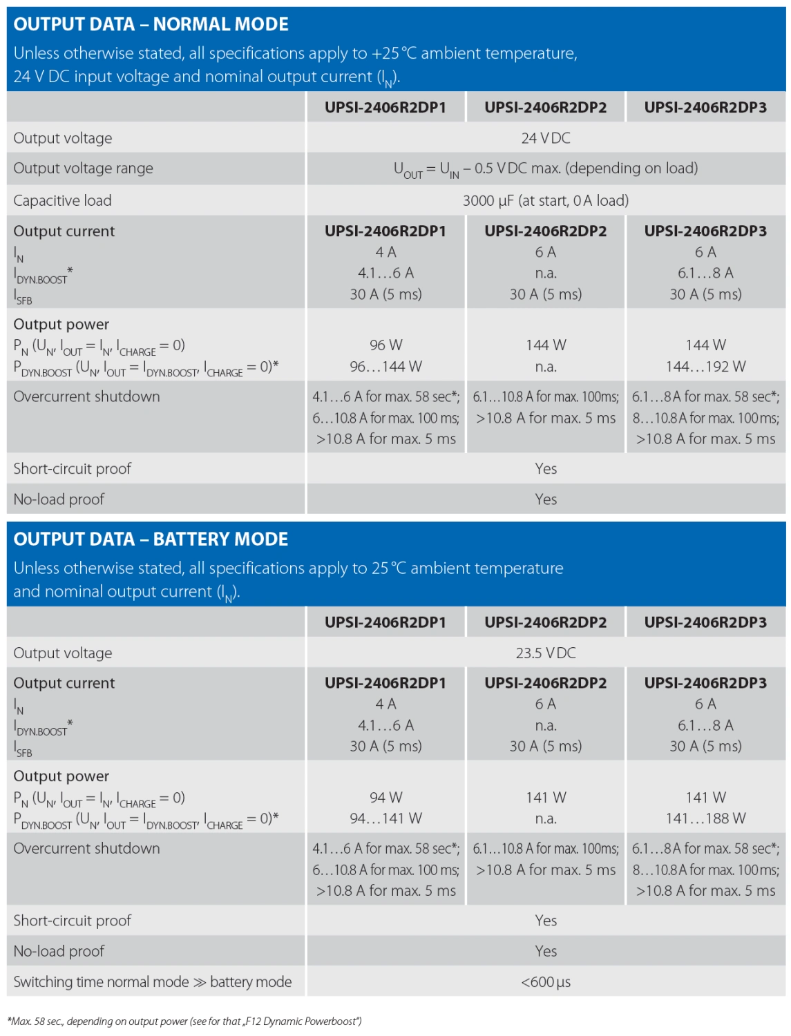
- Output voltage: normal mode ≈ VIN − 0.5 V / backup mode 23.5 VDC regulated
- Output current: 6 A nominal
- Power: 144 W
- Energy storage technology: EDLC / supercapacitors
- Mounting: on DIN rail according to EN 60715
Backup and supercapacitors
- Energy storage capacity: 5.73 kJ / 1.59 Wh nominal; 3.88 kJ / 1.08 Wh usable
- Storage lifetime: up to 500,000 charge and discharge cycles
- Charging method: CC / CV / CP
Output and power
- Switching time: <600 µs
- Capacitive load: max. 3000 µF (during start-up, load 0 A)
Input parameters and power supply
- Max. input current: 6.2 A
Communication and signalling
- Communication interfaces: USB-C (HID-UPS), RS-485 (Modbus RTU)
- Signalling: potential-free relay contact for Power Fail
Functions and protections
- Functions: intelligent input current control (Power Sharing), regulated output voltage in backup mode, minimum load detection, timer on power failure, device restart, energy status indication, shutdown via external signal
- Protections: protection against input polarity reversal, overcurrent and output short circuit
Operating conditions
- Operating temperature: −20 to +65 °C
- Storage temperature: −30 to +65 °C
- Max. humidity: ≤95%, non-condensing
- Max. altitude: 4000 m
Mechanical design
- Protection rating: IP20
- Dimensions (W x H x D): 63 x 120.5 x 105 mm
- Weight: 0.6 kg
Frequently Asked Questions about the Bicker UPSI-2406R2DP2MB DC UPS with supercapacitors
What is UPSI-2406R2DP2MB?
UPSI-2406R2DP2MB is an industrial DC UPS module for 24 V systems with integrated supercapacitors (EDLC). It is designed to bridge short-term power outages and enables safe data storage or controlled system shutdown.
How does a DC UPS work in an industrial system?
The UPS is installed between the power supply and the protected device. In normal operation, it passes the input voltage to the output while simultaneously charging the supercapacitors. In the event of a voltage drop or power failure, it switches very quickly to backup mode (< 600 µs) and supplies the device from its internal energy storage.
What is the difference between UPSI-2406R2DP2MB and UPSI-2406R2DP3MB?
The UPSI-2406R2DP2MB model uses supercapacitors with an extremely long service life of up to 500,000 cycles and very fast charging, but provides a shorter backup time. The UPSI-2406R2DP3MB variant uses a LiFePO4 battery, which offers significantly longer backup duration but has a lower number of cycles and longer charging time.
When should you choose a UPS with supercapacitors?
A supercapacitor-based UPS is ideal for applications requiring short but reliable backup—such as safe data storage, controlled shutdown of IPCs or PLCs, bridging short outages or voltage dips.
What is the energy capacity of UPSI-2406R2DP2MB?
The energy storage has a capacity of 5.73 kJ (approx. 1.59 Wh), of which the usable energy is approximately 3.88 kJ (approx. 1.08 Wh).
How long can the UPS power a device?
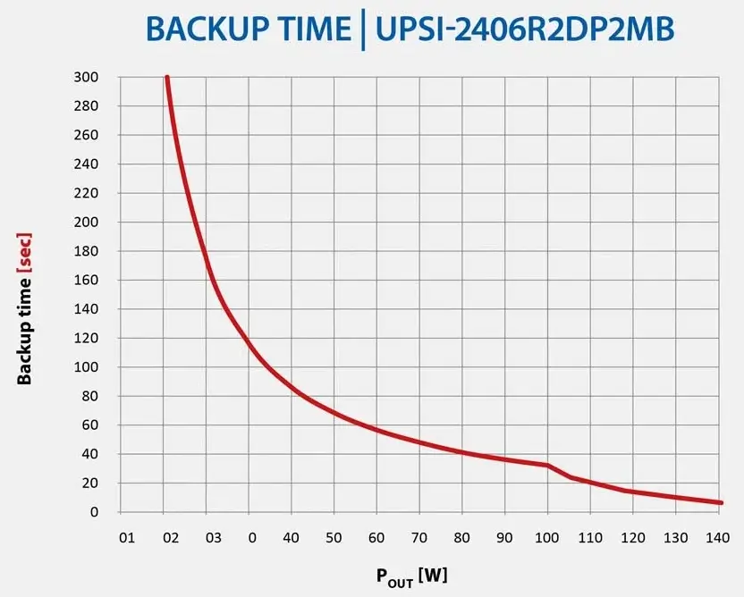
The backup time depends on the connected load. The UPS is designed for short backup durations—typically in the range of seconds (e.g., approx. 8 s at full load of 6 A or tens of seconds at lower loads).
How fast does the UPS recharge?
Thanks to supercapacitor technology, charging is very fast and typically takes about 4–5 minutes after full discharge.
What is the lifetime of a UPS with supercapacitors?
Supercapacitors achieve a lifetime of up to approximately 500,000 charge cycles, which is significantly more than standard battery-based UPS systems.
What output voltage does the UPS provide in backup mode?
In backup mode, the UPS stabilizes the output voltage at approx. 23.5 V DC, independent of the charge level of the supercapacitors.
How does the UPS signal its status?
The device status is indicated by an LED on the front panel and a potential-free relay contact (power fail), which can be connected to a PLC or higher-level system.
How can the UPS be monitored or configured?
The UPS supports communication via USB-C (HID-UPS) and RS-485 with Modbus RTU protocol. Configuration and monitoring are performed using UPS Gen2 Configuration or UPScom software with a web interface.
What power supply is required before the UPS?
It is recommended to use a regulated 24 V DC power supply with sufficient capacity to cover both the load and UPS charging (typically sized with a margin above 6 A plus charging current).
What applications is UPSI-2406R2DP2MB suitable for?
The UPS is suitable for industrial PCs (IPC), PLC systems, communication devices, IoT gateways, measurement equipment, and safety or control systems where high reliability and minimal maintenance are required.
Bicker Review: Jarda Blažek compared 2 smart UPS units with a supercapacitor and a battery
Smart industrial backup power supplies from Bicker protect your production systems and industrial PCs against unexpected power outages, voltage drops, and fluctuations. Jarda Blažek (blaja.cz) investigated the practical differences between UPS units with an integrated supercapacitor and those with a LiFePO4 battery.
Highlighted items are mandatory.