



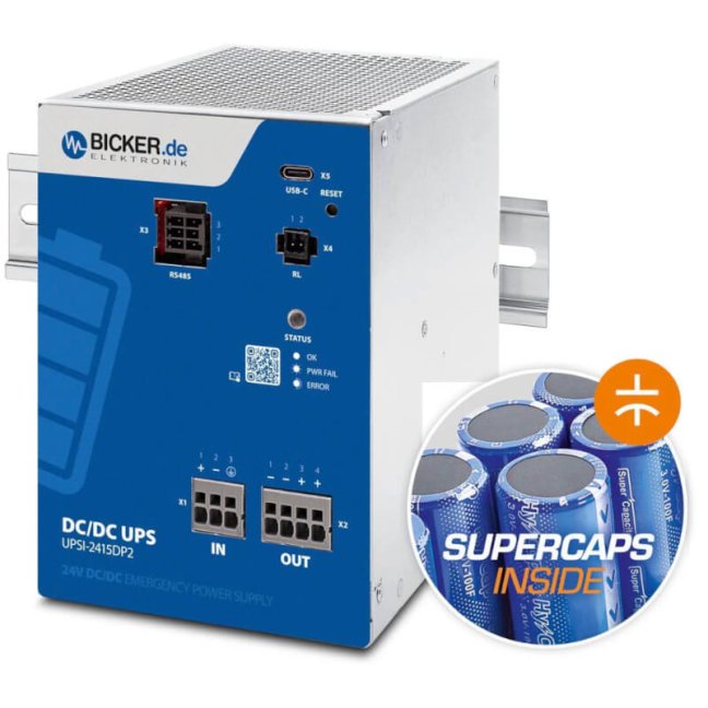
360 W 24 VDC / 15 A UPS backup power supply Bicker with supercapacitor and USB-C + RS485 Modbus interfaces

Smart industrial DC UPS 24 VDC / 15 A, 360 W with integrated supercapacitor, configuration via UPScom software, USB-C and RS485 Modbus interface, DIN rail mounting. More
Code: UPSI-2415DP2
Smart industrial DC UPS 24 VDC / 15 A, 360 W with integrated supercapacitor, configuration via UPScom software, USB-C and RS485 Modbus interface, DIN rail mounting. More
Code: UPSI-2415DP2
Bicker UPSI-2415DP2 · backup power supply with supercapacitors
Protect your 24V devices and data from power outages
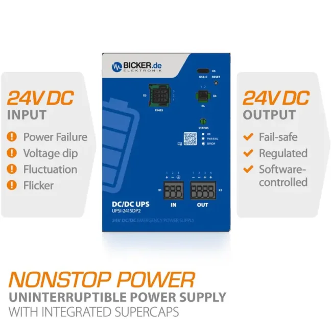
The Bicker UPSI-2415DP2 is a backup power supply for devices powered by 24 V DC. During a brief power outage, it temporarily supplies them from its built-in supercapacitors – energy storage components that recharge quickly and withstand very frequent charging and discharging. It offers 360 W of power and a current of up to 15 A. At this load, the manufacturer specifies approximately 26 seconds of backup time, so the time needed to save data or shut down must be checked for the specific device. It mounts on a DIN rail in a control cabinet. FOXON will help you choose the right unit and arrange worldwide shipping.
How long do you need to keep your devices running during an outage?
Tell us which devices you want to back up and for how long. If you know their power consumption in watts, include it; we will help you choose a suitable backup unit and power supply.
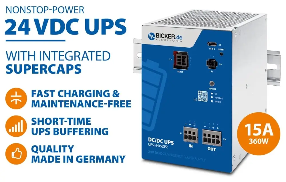
Reliable backup for industrial automation
An uninterruptible power supply, or UPS, helps keep industrial computers, machine controllers (PLCs), network devices and measuring instruments running during brief power outages or voltage fluctuations. It switches to supercapacitor power in less than 3 ms, or three thousandths of a second. In backup mode, it maintains an output voltage of 24.5 VDC ±2 %. When selecting a unit, check the required backup time and whether the connected devices can tolerate this brief switching interval.
Supplies connected 24V devices with up to 15 A. On supercapacitor power, it maintains 24.5 VDC ±2 %.
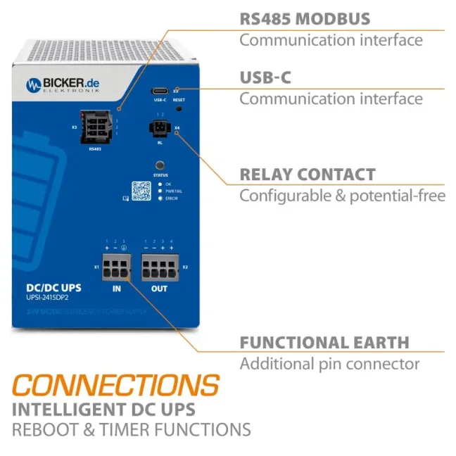
USB-C connects the unit to a computer. RS485 Modbus RTU can send data to a machine controller or monitoring system. A relay contact can also signal a power failure.
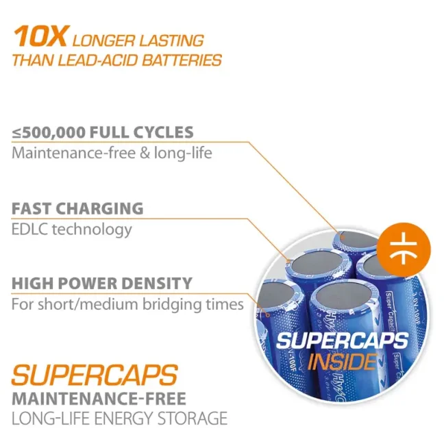
The built-in supercapacitors withstand up to 500 000 charge and discharge cycles. The manufacturer describes them as maintenance-free energy storage, suitable for frequently recurring brief power outages.
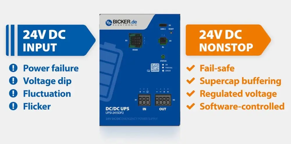
For new control cabinets and upgrades to existing equipment
Use the UPSI-2415DP2 when building a new control cabinet or adding backup power to an existing machine. It helps protect devices powered by 24 V against short outages and voltage fluctuations.
A machine controller, industrial computer or PROFINET or Ethernet network switch can therefore ride through a brief outage without an unnecessary restart. If the outage lasts longer, backup power can provide time to save data or bring the machine to a safe stop – always within the available backup time. DIN rail mounting makes installation in a control cabinet easier.

Supercapacitors: ready for frequent brief power outages
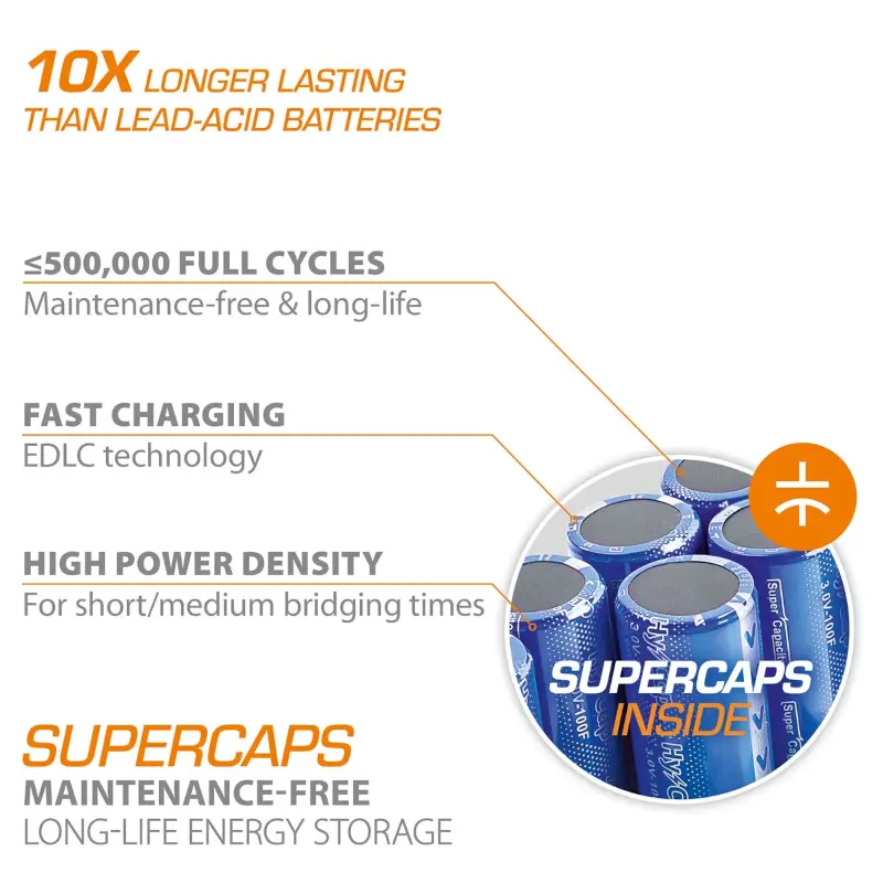
Supercapacitors store electrical energy differently from batteries. Their main advantages are fast charging and a high number of repeated uses: the manufacturer specifies up to 500 000 full charge and discharge cycles. The technical abbreviation EDLC stands for electric double-layer capacitor. The built-in electronics continuously control charging and discharging.
The UPSI-2415DP2 has a nominal energy capacity of 13.5 kJ, equivalent to 3.75 Wh. Its usable capacity is 9.0 kJ, equivalent to 2.5 Wh. It is therefore particularly suitable for brief, frequently recurring outages; a battery UPS is more suitable for extended operation during a mains outage. Actual backup time depends on load, charge level and temperature. The original illustration below compares supercapacitor and lead-acid battery service life in general; the claim of ten times the lifespan is not a service-life guarantee for a specific installation.
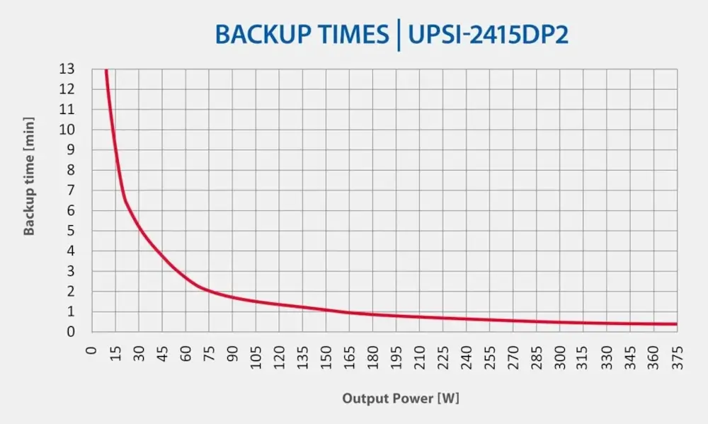
How long will your devices keep running during an outage?
The manufacturer's curve shows backup time against output power at +25 °C. For the UPSI-2415DP2, the manual specifies 26 s at the nominal output current of 15 A. Backup time increases at lower loads: approximate readings from the curve give about 5 min at 30 W and 2 min at 75 W. These are indicative graph readings, not guaranteed times. Actual performance depends on the condition and charge level of the supercapacitors, temperature and UPS settings. When choosing a unit, add up the power consumption of all devices to be backed up and allow a time margin.
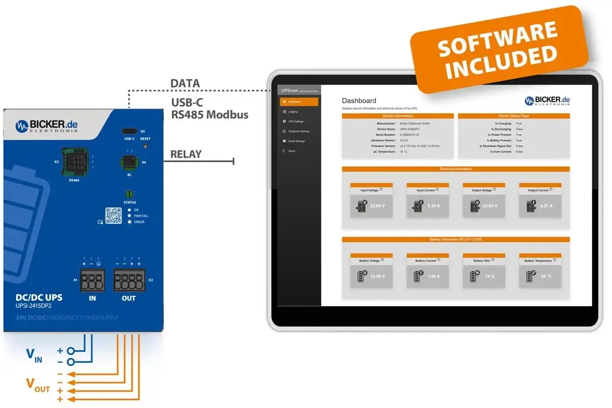
View the charge level and settings in your browser
UPScom lets you view the current supercapacitor charge level and configure how the backup power supply responds to an outage. The program is installed on a computer and operated through a web browser. Versions are available for Windows and Linux.
When connected via USB-C, supported operating systems recognise the device as a UPS without an additional driver. The technical name for this feature is HID Power Class. UPS Gen2 Configuration Software lets you change internal settings and update the firmware — the unit's internal control software — in Windows. Use UPScom for continuous monitoring, email alerts or running your own program before the computer shuts down.
- monitoring current draw in mA and detecting when it drops below a set threshold,
- shutdown delay, maximum backup time and minimum charge before startup,
- email notifications in case of loss of connection, power outage or system shutdown,
- safe shutdown and, if needed, running a custom script — a prepared sequence of commands — before the computer switches off.
Safe shutdown and automatic computer restart
During a power outage, the UPS notifies the connected computer. With the correct settings, the computer can save data, complete predefined tasks and shut down safely. The entire process must finish within the available backup time; at a load of 15 A, the manufacturer specifies 26 s. Once power returns, you can use the automatic restart function, which the manufacturer calls Reboot. Also check the operating system settings and the industrial computer's (IPC's) automatic power-on settings.
USB-C is mainly used for connecting to a computer. The RS485 interface with Modbus RTU allows a machine controller (PLC) or monitoring system (SCADA) to read the UPS status and work with its settings.
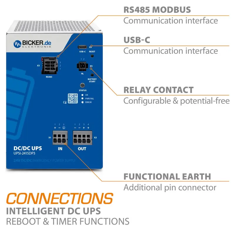
The interface illustration retained from the existing description shows the UPSI-2415DP3. The UPSI-2415DP2 also has USB-C, RS485 and a relay contact; the Battery Start button shown is not present on the DP2 model.
Connections for computers, machines and power failure signalling
Practical features that help in real operation
The UPSI-2415DP2 monitors the load of connected devices and the supercapacitor charge level. Depending on its settings, it can bridge a brief outage or provide time to finish work and shut down, provided sufficient energy is available.
The manual specifies approximately 5 min to charge fully discharged supercapacitors at the maximum charging current. If the UPS simultaneously supplies devices with a high current draw, charging takes longer: the indicative curve shows approximately 10 min at 15 A. According to the manufacturer, recharging immediately after backup operation significantly reduces the time required. There is therefore no fixed charging time for all operating conditions.
Shutdown can be configured according to the remaining charge, maximum permitted backup time, a schedule or a drop in load. The UPS also supports a shutdown command via an external signal. The connected computer or machine controller must complete the necessary tasks before power is disconnected.
The manufacturer specifies an operating temperature of −20 to +65 °C. Provide natural airflow around the UPS and observe the installation clearances in the manual. Very low or high temperatures reduce backup time, so verify the design for the actual conditions inside the control cabinet.
Immunity and protection functions
The UPSI-2415DP2 operates at −20 to +65 °C. The manual lists UL 61010-1 / UL 61010-2-201, CSA C22.2 61010-1-12 / CSA C22.2 61010-2-201 and CB Scheme IEC 61010-1 / IEC 61010-2-201 certifications. Its IP20 rating requires a suitable protective control cabinet; it is not a safety control component.
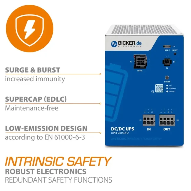
Higher surge immunity helps keep the UPS running even when brief electrical interference pulses or sudden voltage surges occur on the power supply line.
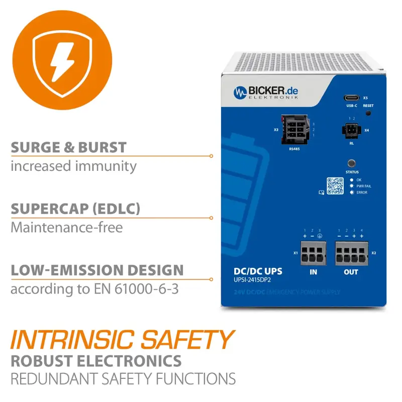
Immunity to short sequences of fast electrical interference pulses according to EN 61000-4-4: 2 kV. Surge immunity according to EN 61000-4-5: ±1 kV between L–N conductors and ±2 kV between L–PE/N–PE. Both tests meet criterion A: the device must operate within the specified limits during testing without affecting the output voltage. Interference generated by the unit itself meets EN 61000-6-3 limits.
Protection against reverse polarity, overcurrent, short circuits and backfeeding into the input. The control electronics supervise supercapacitor charging and discharging. The manufacturer also specifies redundant protective functions in the event of a fault.
The UPS lets you set the power supply duration after an outage and detect a low load from connected devices. Once work is complete, it can disconnect the output and conserve the remaining energy. Energy storage undervoltage protection is also included.
Technical parameters
| Manufacturer's order code | UPSI-2415DP2 |
|---|---|
| Input voltage | 24 VDC, range 23–30 VDC |
| Output | Rated at 24 VDC. During normal operation, the output follows the input voltage with a drop of no more than 0.7 V, depending on current draw. On supercapacitor power, it maintains 24.5 VDC ±2 %. |
| Output current / power | Rated current of 15 A in both modes. Rated output power is 360 W during normal operation and 367.5 W at 24.5 V on supercapacitor power. The manufacturer's power figures apply without simultaneous supercapacitor charging. |
| Output current at increased load (I_STAT.BOOST) | 15.2 A during normal operation and on supercapacitor power; the protective shutdown limits below apply. |
| Power at increased load (P_STAT.BOOST) | 365 W during normal operation; 372.4 W on supercapacitor power. Figures apply at I_STAT.BOOST current and without simultaneous supercapacitor charging; they do not represent a new rated power for the device. |
| Brief output current pulse (I_SFB) | 90 A for 5 ms in both modes. This is a brief pulse, not a continuously available current. |
| Capacitance connected to the output at startup | 10 000 µF at startup if the output is not simultaneously supplying current to connected devices (0 A); specified for normal operation. |
| Output short-circuit protection | Yes, during normal operation and on supercapacitor power. The manufacturer specifies reversible short-circuit protection for normal operation. |
| Operation with no output load | Yes, the unit can operate with no current drawn from the output in both modes. |
| Protective shutdown if current is too high | Current of 15.2–16.8 A: no more than 100 ms before shutdown. Current above 16.8 A: no more than 5 ms before shutdown. Applies during normal operation and on supercapacitor power. |
| Internal output fuse | 15 A; specified in the manufacturer's normal-operation data. |
| Built-in energy storage | EDLC supercapacitors, BP-SUC-30090 module; nominal 13.5 kJ / 3.75 Wh, usable 9.0 kJ / 2.5 Wh; up to 500 000 charge and discharge cycles |
| Switching time | < 3 ms |
| Communication / signalling | USB-C (USB 2.0; HID for UPS recognition, VCOM for a virtual serial port), RS485 Modbus RTU; potential-free relay contact for power failure signalling |
| Mounting and degree of protection | DIN rail EN 60715, IP20 |
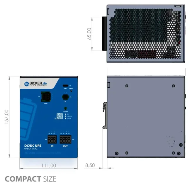
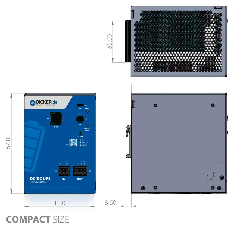
| Dimensions (W × H × D) | 111 × 157 × 150 mm; excluding front connectors and DIN rail bracket |
| Weight | 1.71 kg (UPS unit only) |
| Operating conditions | −20 to +65 °C; max. 95 % relative humidity at +25 °C, non-condensing; up to 4 000 m. Very low or high temperatures reduce backup time. |
| Maximum input current | 17.5 A |
| Backup at rated current | 26 s at 15 A; reference conditions +25 °C |
| Charging | Approximately 5 min at the maximum charging current with fully discharged energy storage; longer at high loads (approximately 10 min at 15 A according to the curve in the manual) |
| Relay contact | 24 VDC / 0.5 A max.; signalling by closing or opening the contact (NO/NC) can be configured in software; for reporting operating status only |
| RS485 Modbus RTU | 38 400 Bd; cable length <100 m; the interface is not electrically isolated from the UPS circuits (no galvanic isolation) |
| Storage / transport | −30 to +70 °C |
| Power supply connected upstream of the UPS | SELV/PELV protective extra-low voltage power supply, min. 24 V / 20 A for full functionality; 500 W recommended |
| Connecting multiple UPS units | Series and parallel connection are not permitted |
| Charging current and method | Max. 5.8 A; CC / CV / CP – controlled charging with current, voltage and power limits |
| Supercapacitor module voltage | Nominal and end-of-charge voltage: 31.3 V; protection when the voltage drops to 16 V. These values apply to the internal energy storage, not the UPS output voltage. |
| USB-C | USB 2.0; cable length no more than 3 m; no galvanic isolation |
| Status indication | Front-panel LED for normal operation, power failure and faults; relay contact for power-failure indication |
Technical data: Bicker UPSI-2415DPx manual, revision 1-1 dated 26 May 2026, particularly chapters D1 and E. Reference measurement conditions: +25 °C, 24 VDC input and rated current, unless stated otherwise. Open the manufacturer's manual (PDF) ↗
Scope of delivery
- 1× UPSI-2415DP2 backup power supply with built-in supercapacitors
- 1× RS485 (Modbus) mating connector
- 1× relay mating connector
Contents according to chapter E7 of the manual. Select the power supply and connection cables separately to suit your devices; we will be happy to help.

About the manufacturer
Bicker Elektronik
Bicker Elektronik is a German manufacturer that has been developing, manufacturing and supplying industrial power supplies, UPS backup systems and system components since 1994.
Bicker products are used in automated machines, robots, measuring instruments, production data collection equipment, medical equipment and communication systems, among other applications. For the UPSI-2415DP2, the manufacturer focuses on long-term operation in control cabinets, connections to other equipment and backup power for important devices.
Frequently Asked Questions
How long can the UPSI-2415DP2 keep a device running during an outage?
The manual specifies 26 s at the nominal current of 15 A under reference conditions of +25 °C. Backup time increases at lower loads; charge level, temperature and settings also affect it. Send us the total power consumption of your devices and the required operating time during an outage – we will help you choose the right unit.
Can a machine controller monitor the UPS status?
Yes. RS485 Modbus RTU can send information to a machine controller (PLC) or monitoring system (SCADA). USB-C also connects the unit to an industrial computer, where a supported operating system recognises it as a UPS (HID-UPS).
Can the unit be started manually without input power?
The UPSI-2415DP2 does not support manual startup from its energy storage without input power. The manual lists this function, called Battery Start, only for the battery-powered UPSI-2415DP3 model. Automatic backup during an outage and restarting when power returns are separate functions.
What happens when current draw is low or the energy storage is discharged?
The UPS detects when the current draw falls below a set threshold. After connected devices have shut down safely, it can disconnect their power and prevent unnecessary consumption of the remaining energy. The energy storage also has undervoltage protection.
Should you choose a UPS with a battery or a supercapacitor?
A LiFePO₄ battery is suitable for longer operation during an outage. A supercapacitor is a different way of storing electrical energy: it is mainly suited to short, very frequent outages. The main factor when choosing is how long your devices need to work without the main power supply.
Can this UPS safely shut down any computer?
Not automatically. You need to measure the power consumption and the time required for the specific computer to save data and shut down. At 15 A, the UPSI-2415DP2 provides 26 s of backup according to the manual; if you need more time, choose a suitable battery version. Test the settings and the entire procedure under your application's operating conditions.
Is the relay intended for safety circuits?
No. The potential-free contact is for operational signalling, rated at 24 VDC / 0.5 A maximum. The manufacturer explicitly prohibits using this contact to implement safety-critical circuits.
Do you ship UPS units outside the Czech Republic?
Yes, we ship products worldwide. Tell us the quantity, country and delivery location. We will check availability and provide a specific shipping quotation and delivery estimate.
Why buy from FOXON
Want to protect your devices from power outages?
Tell us what you want to back up, for how long and where we should deliver the unit. If you know your devices' power consumption and the required connection to a computer or machine, include those details. We will help you choose and prepare a quotation including shipping. We ship worldwide.
Request a solutionUPS configuration via USB
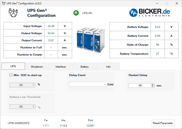
Connect the UPSI-2415DP2 to your computer using a USB cable. In UPS Gen² Configuration, you can configure UPS behaviour and view its operating data. The screenshots below show the individual program tabs.
The UPSI-2415DP2 stores energy in EDLC supercapacitors. Battery labels in the program refer to this energy storage device, not to a Li-Ion battery. Click an image to open it separately for a detailed view. The values shown are examples of a specific configuration and operating state.
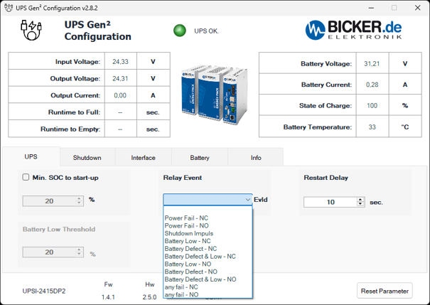
The power and energy storage overview at the top and the identification bar at the bottom appear in all five screenshots. These are read-only data; settings are changed in the individual tabs.
Common information on all screens
- Input Voltage [V]
- UPS input voltage. This value is available during normal operation from the upstream power supply.
- Output Voltage [V]
- Voltage at the UPS output supplying the connected equipment. It is displayed during both normal and backup operation.
- Output Current [A]
- Current drawn by the equipment connected to the UPS output.
- Runtime to Full [sec.]
- Estimated time until the supercapacitor energy storage device is fully charged. These screenshots show the time in seconds, not minutes.
- Runtime to Empty [sec.]
- Estimated remaining backup time under the current load, shown here in seconds. This is not a guaranteed operating time. Dashes mean that the program is not currently displaying an estimate.
- Battery Voltage [V]
- Current voltage of the supercapacitor energy storage device. It is not the same as the UPS output voltage.
- Battery Current [A]
- Energy storage current. A positive value indicates charging; a negative value indicates discharging.
- State of Charge [%]
- Current state of charge of the supercapacitor energy storage device, abbreviated SOC. The percentage thresholds for startup and shutdown use this value.
- Battery Temperature [°C]
- Temperature reported for the energy storage device. For the DP2, this relates to the supercapacitor module, not the UPS processor temperature.
- Status indicator and UPS OK.
- Indication of the current UPS operating state. The example shows a green indicator and the message UPS OK.
- Program name and version
- The title bar shows the configuration program name and version. The screenshots show UPS Gen² Configuration v2.8.2.
- UPS / Shutdown / Interface / Battery / Info
- Tabs for UPS settings, shutdown conditions, communication interfaces, energy storage data and device identification. The operating data overview at the top remains the same on all five screens.
- Device identification
- The connected UPS model is shown at the bottom left, here UPSI-2415DP2.
- Fw
- Version of the firmware installed in the UPS. The screenshots show 1.4.1. This is different from the version of the program on the computer.
- Hw
- UPS hardware version. The screenshots show 2.5.0.
- Port
- Port used for the USB-C connection between the program and the UPS, here COM7. This is a virtual serial port on the computer, not a device address on the Modbus network.
- Save Parameter
- Function for saving modified parameters to the UPS. The configuration program can be closed after saving. The Save Parameter button is not shown in these screenshots.
- Reset Parameter
- Restores the default configuration parameter values. This is neither a normal save operation nor the physical Reset button on the UPS, which restarts its microcontroller.
UPS tab settings
- Min. SOC to start-up [%]
- Minimum energy storage charge required to enable the UPS output. After being switched on or restarted, the UPS waits until the supercapacitors reach the set charge level before allowing power to the load. The screenshot shows 20 %, but the option is not checked.
- Battery Low Threshold [%]
- Low energy storage charge threshold for relay signalling. The screenshot shows 20 % and the field is inactive. This threshold is used for charge signalling; it is separate from the command to shut down the operating system.
- Restart Delay [sec.]
- Time for which the output remains off during a restart sequence before being switched on again. It provides a defined off period during which capacitances in the connected equipment can discharge. The screenshot shows 10 seconds. Automatic computer startup also requires the appropriate BIOS settings.
- Relay Event / EvId
- Selects the event signalled by the potential-free UPS relay contact. EvId denotes the event identifier. The menu is expanded in the screenshot and the field at the top does not show a selected event. The contact can report status to a PLC, for example; its maximum load is 24 V DC / 0.5 A. Do not use it for safety-critical circuits.
Relay Event menu options
- Power Fail - NC
- Input power failure indication with NC contact logic. Verify the actual contact state during normal and backup operation for the firmware used.
- Power Fail - NO
- Input power failure indication with NO contact logic. Verify the actual contact state during normal and backup operation for the firmware used.
- Shutdown Impuls
- A short relay pulse to initiate computer shutdown. The relay is connected in parallel with the computer's power button. The pulse is associated with enabled shutdown by time or SOC.
- Battery Low - NC / Battery Low - NO
- Relay signalling of low charge according to Battery Low Threshold. NC and NO designate different contact logic. The actual contact state when the threshold is reached must be confirmed for the firmware used.
- Battery Defect - NC / Battery Defect - NO
- Relay signalling of a missing or unrecognised energy storage device. The NC and NO variants differ in their contact logic; the exact conditions and contact state must be confirmed for the firmware used.
- Battery Defect & Low - NC / Battery Defect & Low - NO
- Names of options for combined signalling of an energy storage fault and low charge. The exact combination of trigger conditions and the contact state must be confirmed for the firmware used.
- any fail - NC / any fail - NO
- Options for combined fault indication with NC or NO contact logic. Verify the exact list of included events and the contact state for the firmware used; the name any fail alone does not define them.
NC means Normally Closed; NO means Normally Open. Relay settings depend on the supported UPS hardware and firmware version. Before connecting the relay to a machine control system, we will help verify the required event and the resulting contact logic.
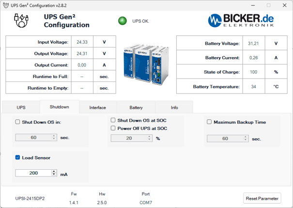
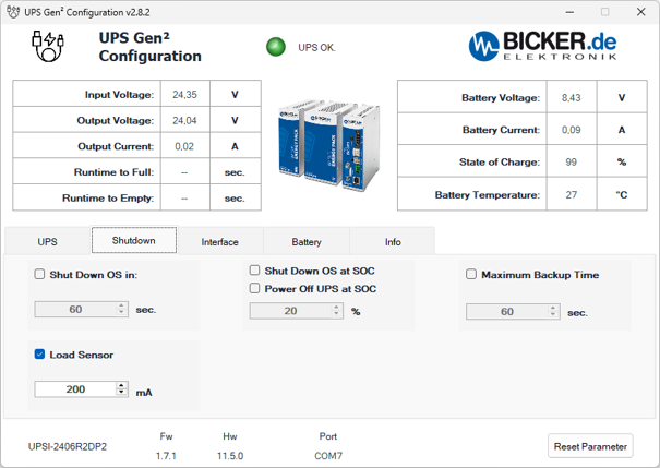
The upper section again displays power supply data, load current, energy storage charge and temperature; the bottom bar identifies the UPS, firmware, hardware and communication port. The Shutdown tab determines when computer shutdown begins or the UPS output is disconnected.
- Shut Down OS in [sec.]
- Time from the start of backup operation until the command to shut down the operating system is sent. If input power returns sooner, the timed shutdown condition does not take effect. The screenshot shows 60 seconds, but the option is not checked.
- Load Sensor [mA]
- Low load detection. If the load current falls below the set limit during backup operation, the UPS switches off its output and disconnects the energy storage device to limit discharge. In the screenshot, the function is enabled with a threshold of 200 mA.
- Shut Down OS at SOC [%]
- Initiates operating system shutdown when charge falls below the set threshold while the UPS is still running on supercapacitor power. The screenshot shows 20 %, but the option is not enabled.
- Power Off UPS at SOC
- Option for switching off the UPS according to its state of charge. It is separate from the Shut Down OS at SOC command. Its exact threshold and interaction with operating system shutdown must be confirmed for the firmware used; the option is not enabled in the screenshot.
- Maximum Backup Time [sec.]
- Maximum permitted backup operating time. When the configured limit expires, the UPS disconnects power to the load. The screenshot shows 60 seconds, but the function is not enabled. The limit does not guarantee that the stored energy will last that long. For a computer, allow enough time for the operating system to shut down completely before disconnecting the output.
- Checkboxes
- Enable or disable the corresponding condition. A number shown in an unchecked field does not by itself mean that the function is active.
Using time and charge thresholds together: if both Shut Down OS in and Shut Down OS at SOC are enabled, whichever condition occurs first triggers shutdown.
Windows settings: for shutdown via USB HID, set the power button action to Shut down. Disable automatic sleep while powered by the UPS; otherwise its low current draw could activate Load Sensor.
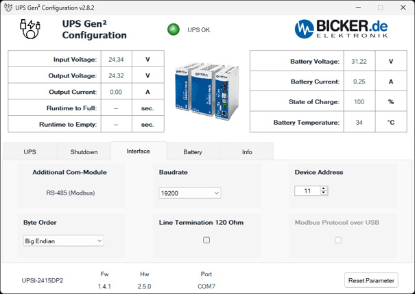
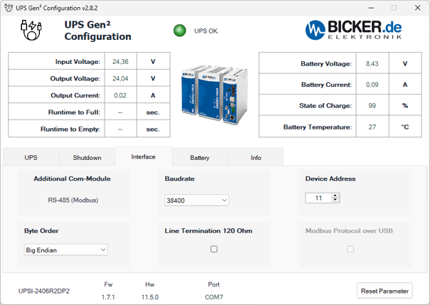
In addition to USB-C, the UPSI-2415DP2 has an RS485 interface with Modbus RTU. The configuration program connects via USB; this tab configures communication with a PLC or another Modbus client. The values in the screenshot are examples, not universal settings for every network.
- Additional Com-Module
- Type of additional communication interface. The screenshot shows RS-485 (Modbus), matching the interface of this UPS model.
- RS-485 (Modbus)
- Serial link for Modbus RTU communication, for example with a PLC or SCADA system. This is neither an RS232 interface nor Modbus TCP over Ethernet.
- Baudrate
- RS485 line transmission rate. The screenshot shows 19200 baud. The rate must match the settings of the other devices on the same line.
- Device Address
- Device address on the Modbus network. The screenshot shows 11. The client must use the same address, and individual devices on the line must have different addresses. This is not the USB port number COM7.
- Byte Order
- Byte order used when transferring data. The screenshot shows Big Endian, meaning the most significant byte is sent first. The setting must match how the client processes data; this option alone does not define the register map or the order of multiple registers within a value.
- Line Termination 120 Ohm
- Option for terminating the RS485 line with a 120 Ω resistor. It is unchecked in the screenshot. Termination is used at both ends of the main line, not automatically at every device; it depends on the actual bus wiring.
- Modbus Protocol over USB
- Option for selecting Modbus communication over USB. It is inactive and unchecked in the screenshot. This example does not confirm that the mode is available for the firmware used; support must be verified before use.
- Port COM7
- Virtual serial port used for the USB-C connection between the configuration program and the UPS. It is independent of the Modbus device address and is not a device number on the RS485 line.
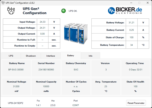
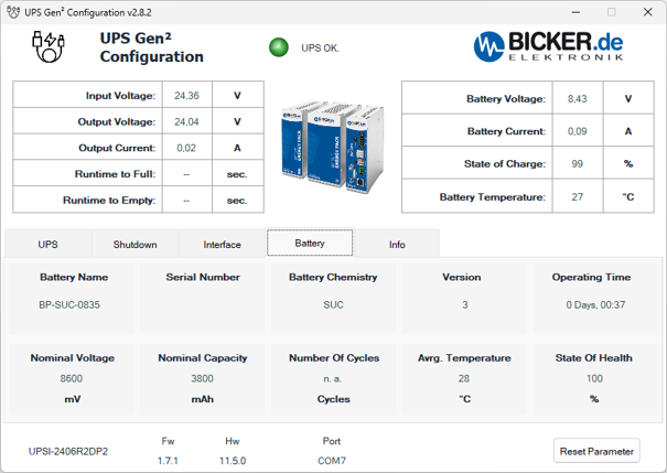
The Battery tab displays identification and operating data for the supercapacitor energy storage device. It is not a form for changing the storage type or capacity. The upper overview continues to show its instantaneous voltage, current, charge and temperature.
- Battery Name
- Designation of the connected energy storage device. The example shows BP-SUC-30090, the supercapacitor module used in the UPSI-2415DP2.
- Serial Number
- Serial number reported by the energy storage device. The screenshot shows 2341B0190060. It identifies the supercapacitor module, not the UPS itself; the UPS serial number is on the Info tab.
- Battery Chemistry
- Energy storage technology. SUC in the example denotes supercapacitors, or EDLC. It does not designate a Li-Ion battery.
- Version
- Version reported by the energy storage module, here 3. This is neither the configuration program version nor the firmware version of the entire UPS.
- Operating Time
- Displayed operating time counter in days, hours and minutes; the example shows 0 Days, 02:01. This value alone does not establish the energy storage device's manufacturing date or age.
- Nominal Voltage [mV]
- Nominal voltage reported by the energy storage module in millivolts; the screenshot shows 31200 mV. It is separate from the instantaneous Battery Voltage and the UPS output voltage. The displayed value is data from the specific module, not a change to the catalogue specification.
- Nominal Capacity [mAh]
- Capacity field reported by the module. The program displays 10000 mAh here even though the storage device uses supercapacitors. Do not interpret this as a Li-Ion battery capacity or convert it to farads without supporting data. For backup design, use the nominal and usable storage energy in kJ or Wh and the backup time at the actual load.
- Number of Cycles [Cycles]
- The SUC energy storage device does not provide the full charge and discharge cycle count here. The screenshot shows n. a.; this does not mean zero cycles or indicate the supercapacitors' remaining service life.
- Avg. Temperature [°C]
- Average temperature reported in the energy storage overview. It is different from the instantaneous Battery Temperature at the top of the window.
- State of Health [%]
- Energy storage health indicator, abbreviated SOH. Do not confuse it with SOC, the current state of charge. SOH support must be confirmed for the specific supercapacitor module and firmware; a displayed value of 100 % alone does not confirm measured usable energy or remaining service life.
The values in the screenshot relate to one specific connected setup. When designing a backup system, use the specifications of the supplied UPSI-2415DP2 and its supercapacitor energy storage device rather than the figures in this program example.
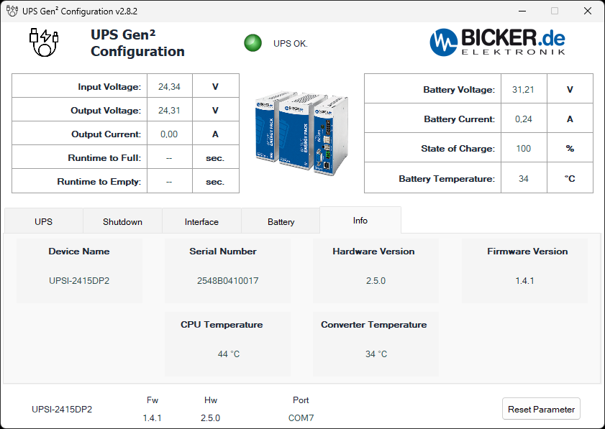
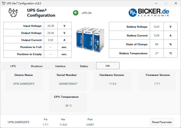
This tab summarises the information needed for device identification, version checks and technical support. The upper section displays the same power supply and energy storage operating data as the previous screens.
- Device Name
- Model of the connected UPS. The screenshot shows UPSI-2415DP2.
- Serial Number
- Serial number of the UPS itself, used to identify the individual unit for technical support or servicing.
- Hardware Version
- UPS hardware version, here 2.5.0. The same value appears as Hw in the bottom bar.
- Firmware Version
- UPS internal firmware version, here 1.4.1. The same value appears as Fw in the bottom bar. This is not the version of the configuration program on the computer. Any update must be selected for the exact UPS model and hardware version.
- CPU Temperature [°C]
- Temperature of the processor in the UPS control electronics. This is neither the supercapacitor energy storage temperature nor the temperature of the connected computer.
- Bottom bar and Reset Parameter
- The model, Fw, Hw and Port repeat the identification and connection information. Reset Parameter restores the default UPS parameters; its meaning remains the same when switching tabs.
- Converter Temperature [°C]
- Temperature reported for the central DC/DC converter inside the UPS; the screenshot shows 34 °C. This is separate from CPU Temperature (44 °C) and Battery Temperature. The UPS monitors converter temperature for thermal protection. The displayed value is neither the ambient temperature nor the maximum permitted operating temperature.
Schedule an online meeting
Need help with backup time, wiring or connecting the unit to your devices? Choose a time for a short online consultation directly in the calendar below.
Technical parameters
Basic features
- Device type: intelligent DC UPS module for 24 V systems
- Input voltage: 24 VDC (range 23–30 V)
- Output voltage: normal mode ≈ VIN − 0.6 V / backup mode 24.5 VDC regulated
- Output current: 15 A nominal
- Power: 360 W
- Energy storage technology: EDLC / supercapacitors
- Mounting: on DIN rail according to EN 60715
Backup and supercapacitors
- Energy storage capacity: 13.5 kJ / 3.75 Wh nominal; 9.0 kJ / 2.5 Wh usable
- Storage lifetime: up to 500,000 charge and discharge cycles
- Charging method: CC / CV / CP
Output and power
- Switching time: <3 ms
- Capacitive load: max. 10,000 µF (during start-up, load 0 A)
Input parameters and power supply
- Max. input current: 17.5 A
Communication and signalling
- Communication interfaces: USB-C (HID-UPS), RS-485 (Modbus RTU)
- Signalling: potential-free relay contact for Power Fail
Functions and protections
- Functions: intelligent input current control, regulated output voltage in backup mode, minimum load detection, timer on power failure, device restart, energy status indication, shutdown via external signal
- Protections: protection against overcurrent and output short circuit
Operating conditions
- Operating temperature: −20 to +65 °C
- Storage temperature: −30 to +70 °C
- Max. humidity: ≤95%, non-condensing
- Max. altitude: 4000 m
Mechanical design
- Protection rating: IP20
- Dimensions (W x H x D): 111 x 157 x 150 mm
- Weight: 1.71 kg
Frequently Asked Questions about the Bicker UPSI-2415DP2 Backup Power Supply with Supercapacitors
What is UPSI-2415DP2?
The UPSI-2415DP2 is an industrial DC UPS module for 24 V systems with integrated supercapacitors (EDLC). It is designed to bridge short-term power outages and enables safe data storage or controlled shutdown of equipment.
How does a DC UPS work in an industrial system?
The UPS is installed between the power supply and the protected device. During normal operation, it passes the input voltage to the output while simultaneously charging the energy storage. In the event of a voltage drop or power failure, it switches to backup mode within a few milliseconds (< 3 ms).
What is the difference between UPSI-2415DP2 and UPSI-2415DP3?
The UPSI-2415DP2 uses supercapacitors with an extremely long lifetime of up to 500,000 cycles, but provides a shorter backup time. The UPSI-2415DP3 model uses a LiFePO4 battery with a capacity of 64 Wh, enabling a longer backup duration.
When should a supercapacitor UPS be used?
A supercapacitor-based UPS is suitable for applications requiring short-term backup power – for example, safe data storage and controlled shutdown of an industrial PC or PLC.
What is the energy capacity of the UPSI-2415DP2?
The energy storage has a capacity of approximately 13.5 kJ (approx. 3.75 Wh), of which the usable energy is approximately 9.0 kJ (approx. 2.5 Wh).
How long can the UPS power a device?
The backup time depends on the connected load. The UPS is designed primarily for short backup durations – typically tens of seconds (e.g. approx. 26 s at nominal load).
How fast does the UPS recharge?
Thanks to supercapacitor technology, recharging is very fast and typically takes around 5 minutes from full discharge.
What is the lifetime of a supercapacitor UPS?
Supercapacitors can achieve a lifetime of up to approximately 500,000 charge cycles, which is significantly more than conventional batteries.
What voltage does the UPS provide in backup mode?
In backup mode, the UPS regulates the output voltage to 24.5 V DC.
How does the UPS indicate its status?
The device status is indicated by an LED on the front panel and also via a relay contact that can inform a PLC or higher-level system about a power failure.
How can the UPS be monitored or configured?
The UPS supports communication via USB (HID-UPS) or RS-485 with Modbus RTU protocol. Configuration can be performed using UPS Gen2 Configuration or UPScom software.
What power supply is required before the UPS?
It is recommended to use a 24 V DC power supply with sufficient power, at least 24 V / 20 A (approx. 500 W recommended), capable of supplying the connected device while also charging the UPS energy storage.
What applications is the UPSI-2415DP2 suitable for?
The UPS is used, for example, for industrial PCs, PLC systems, communication devices, industrial gateways, or control electronics.
Bicker Review: Jarda Blažek compared 2 smart UPS units with a supercapacitor and a battery
Smart industrial backup power supplies from Bicker protect your production systems and industrial PCs against unexpected power outages, voltage drops, and fluctuations. Jarda Blažek (blaja.cz) investigated the practical differences between UPS units with an integrated supercapacitor and those with a LiFePO4 battery.
Highlighted items are mandatory.