

3RT1466-6AP36
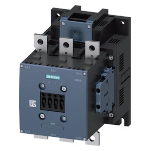
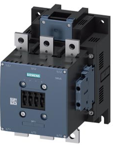


3RT1466-6AP36

Power contactor AC-1 400 A / 690 V / 40 °C 3-pole, Uc: 220-240 V AC(50-60 Hz) / DC drive: conventional auxiliary contacts 2 NO + 2 NC main circuit: busbar control and auxiliary circuit: screw terminal More
Code: 3RT1466-6AP36
Power contactor AC-1 400 A / 690 V / 40 °C 3-pole, Uc: 220-240 V AC(50-60 Hz) / DC drive: conventional auxiliary contacts 2 NO + 2 NC main circuit: busbar control and auxiliary circuit: screw terminal More
Code: 3RT1466-6AP36
Part Sales 1
| Condition | Code | Warranty | Availability |
Delivery Express? | Price excl. VAT | |
|---|---|---|---|---|---|---|
| New in sealed box (NC) | 3RT1466-6AP36 NC | 12/24 months | In external stock 2 pcs |
Within 2-4 days / Express
|
On request
|
Repair of the part
| Name | Code | Delivery | Warranty | Price excl. VAT | |
|---|---|---|---|---|---|
| Complete part repair | 3RT1466-6AP36 O | 3-6 weeks | 24 months | On request | Enquire a repair |
3RT1466-6AP36 – Power contactor
Power contactor.
Need to buy or repair this part?
We will check replacement part availability and the options for diagnosing and repairing your faulty unit.
Application and selection
Compare the complete order number and specifications below with the original part and machine wiring. Check the design, interfaces, supply voltage or connection method as applicable to this product.
Technical specifications
| Manufacturer | Siemens |
|---|---|
| Order number | 3RT1466-6AP36 |
| product brand name | SIRIUS |
| product designation | Contactor |
| product type designation | 3RT14 |
| General technical data / size of contactor | S10 |
| General technical data / product extension / function module for communication | No |
| General technical data / product extension / auxiliary switch | Yes |
| General technical data / power loss [W] for rated value of the current / at AC in hot operating state | 105.6 W |
| General technical data / power loss [W] for rated value of the current / at AC in hot operating state per pole | 35.2 W |
| General technical data / power loss [W] for rated value of the current / without load current share typical | 7.4 W |
| General technical data / type of calculation of power loss current-dependent | quadratic |
| General technical data / insulation voltage / of main circuit with degree of pollution 3 rated value | 1 000 V |
| General technical data / insulation voltage / of auxiliary circuit with degree of pollution 3 rated value | 500 V |
| General technical data / surge voltage resistance / of main circuit rated value | 8 kV |
| General technical data / surge voltage resistance / of auxiliary circuit rated value | 6 kV |
| General technical data / shock resistance at rectangular impulse / at AC | 8,5 g / 5 ms, 4,2 g / 10 ms |
| General technical data / shock resistance at rectangular impulse / at DC | 8,5 g / 5 ms, 4,2 g / 10 ms |
| General technical data / shock resistance with sine pulse / at AC | 13,4 g / 5 ms, 6,5 g / 10 ms |
| General technical data / shock resistance with sine pulse / at DC | 13,4 g / 5 ms, 6,5 g / 10 ms |
| General technical data / mechanical service life (operating cycles) / of contactor typical | 10 000 000 |
| General technical data / mechanical service life (operating cycles) / of the contactor with added electronically optimized | 5 000 000 |
| General technical data / mechanical service life (operating cycles) / of the contactor with added auxiliary switch block typical | 10 000 000 |
| General technical data / reference code according to IEC 81346-2 | Q |
| General technical data / Substance Prohibitance (day/month/year) | 05/01/2012 |
| General technical data / SVHC substance name | Lead CAS-No. 7439-92-1 |
| General technical data / Net Weight | 6.163 kg |
| Ambient conditions / installation altitude at height above sea level maximum | 2 000 m |
| Ambient conditions / ambient temperature / during operation | -25 ... +60 °C |
| Ambient conditions / ambient temperature / during storage | -55 ... +80 °C |
| Ambient conditions / relative humidity minimum | 10 % |
| Ambient conditions / relative humidity at 55 °C according to IEC 60068-2-30 | 95 % |
| Main circuit / number of poles for main current circuit | 3 |
| Main circuit / number of NO contacts for main contacts | 3 |
| Main circuit / number of NC contacts for main contacts | 0 |
| Main circuit / type of voltage for main current circuit | AC |
| Main circuit / operational current / at AC-1 / up to 690 V at ambient temperature 40 °C rated | 400 A |
| Main circuit / operational current / at AC-1 / up to 690 V at ambient temperature 55 °C rated | 380 A |
| Main circuit / operational current / at AC-1 / up to 690 V at ambient temperature 60 °C rated | 380 A |
| Main circuit / operational current / at AC-3 / at 400 V rated value | 138 A |
| Main circuit / operational current / at AC-3 / at 690 V rated value | 138 A |
| Main circuit / minimum cross-section in main circuit at maximum AC-1 rated | 240 mm² |
| Main circuit / operational current / at 1 current path at DC-1 / at 24 V rated value | 380 A |
| Main circuit / operational current / at 1 current path at DC-1 / at 60 V rated value | 380 A |
| Main circuit / operational current / at 1 current path at DC-1 / at 110 V rated value | 33 A |
| Main circuit / operational current / at 1 current path at DC-1 / at 220 V rated value | 3.8 A |
| Main circuit / operational current / at 1 current path at DC-1 / at 440 V rated value | 0.9 A |
| Main circuit / operational current / at 1 current path at DC-1 / at 600 V rated value | 0.6 A |
| Main circuit / operational current / with 2 current paths in series at DC-1 / at 24 V rated value | 380 A |
| Main circuit / operational current / with 2 current paths in series at DC-1 / at 60 V rated value | 380 A |
| Main circuit / operational current / with 2 current paths in series at DC-1 / at 110 V rated value | 380 A |
| Main circuit / operational current / with 2 current paths in series at DC-1 / at 220 V rated value | 380 A |
| Main circuit / operational current / with 2 current paths in series at DC-1 / at 440 V rated value | 4 A |
| Main circuit / operational current / with 2 current paths in series at DC-1 / at 600 V rated value | 2 A |
| Main circuit / operational current / with 3 current paths in series at DC-1 / at 24 V rated value | 380 A |
| Main circuit / operational current / with 3 current paths in series at DC-1 / at 60 V rated value | 380 A |
| Main circuit / operational current / with 3 current paths in series at DC-1 / at 110 V rated value | 380 A |
| Main circuit / operational current / with 3 current paths in series at DC-1 / at 220 V rated value | 380 A |
| Main circuit / operational current / with 3 current paths in series at DC-1 / at 440 V rated value | 11 A |
| Main circuit / operational current / with 3 current paths in series at DC-1 / at 600 V rated value | 5.2 A |
| Main circuit / operational current / at 1 current path at DC-3 at DC-5 / at 24 V rated value | 380 A |
| Main circuit / operational current / at 1 current path at DC-3 at DC-5 / at 60 V rated value | 11 A |
| Main circuit / operational current / at 1 current path at DC-3 at DC-5 / at 110 V rated value | 3 A |
| Main circuit / operational current / at 1 current path at DC-3 at DC-5 / at 220 V rated value | 0.6 A |
| Main circuit / operational current / at 1 current path at DC-3 at DC-5 / at 440 V rated value | 0.18 A |
| Main circuit / operational current / at 1 current path at DC-3 at DC-5 / at 600 V rated value | 0.125 A |
| Main circuit / operational current / with 2 current paths in series at DC-3 at DC-5 / at 24 V rated value | 380 A |
| Main circuit / operational current / with 2 current paths in series at DC-3 at DC-5 / at 60 V rated value | 380 A |
| Main circuit / operational current / with 2 current paths in series at DC-3 at DC-5 / at 110 V rated value | 380 A |
| Main circuit / operational current / with 2 current paths in series at DC-3 at DC-5 / at 220 V rated value | 2.5 A |
| Main circuit / operational current / with 2 current paths in series at DC-3 at DC-5 / at 440 V rated value | 0.65 A |
| Main circuit / operational current / with 2 current paths in series at DC-3 at DC-5 / at 600 V rated value | 0.37 A |
| Main circuit / operational current / with 3 current paths in series at DC-3 at DC-5 / at 24 V rated value | 380 A |
| Main circuit / operational current / with 3 current paths in series at DC-3 at DC-5 / at 60 V rated value | 380 A |
| Main circuit / operational current / with 3 current paths in series at DC-3 at DC-5 / at 110 V rated value | 380 A |
| Main circuit / operational current / with 3 current paths in series at DC-3 at DC-5 / at 220 V rated value | 380 A |
| Main circuit / operational current / with 3 current paths in series at DC-3 at DC-5 / at 440 V rated value | 1.4 A |
| Main circuit / operational current / with 3 current paths in series at DC-3 at DC-5 / at 600 V rated value | 0.75 A |
| Main circuit / no-load switching frequency / at AC | 2 000 1/h |
| Main circuit / no-load switching frequency / at DC | 2 000 1/h |
| Main circuit / operating frequency / at AC-1 maximum | 600 1/h |
| Control circuit/ Control / type of voltage | AC/DC |
| Control circuit/ Control / type of voltage of the control supply voltage | AC/DC |
| Control circuit/ Control / control supply voltage at AC / at 50 Hz rated value | 220 ... 240 V |
| Control circuit/ Control / control supply voltage at AC / at 60 Hz rated value | 220 ... 240 V |
| Control circuit/ Control / control supply voltage at DC rated value | 220 ... 240 V |
| Control circuit/ Control / magnet coil at DC / initial value | 0.8 |
| Control circuit/ Control / magnet coil at DC / full-scale value | 1.1 |
| Control circuit/ Control / magnet coil at AC / at 50 Hz | 0.8 ... 1.1 |
| Control circuit/ Control / magnet coil at AC / at 60 Hz | 0.8 ... 1.1 |
| Control circuit/ Control / design of the surge suppressor | with varistor |
| Control circuit/ Control / apparent pick-up power / at minimum rated control supply voltage at AC / at 50 Hz | 490 V·A |
| Control circuit/ Control / apparent pick-up power / at minimum rated control supply voltage at AC / at 60 Hz | 490 V·A |
| Control circuit/ Control / apparent pick-up power / at maximum rated control supply voltage at AC / at 60 Hz | 590 V·A |
| Control circuit/ Control / apparent pick-up power / at maximum rated control supply voltage at AC / at 50 Hz | 590 V·A |
| Control circuit/ Control / apparent pick-up power of magnet coil at AC / at 50 Hz | 590 V·A |
| Control circuit/ Control / inductive power factor with closing power of the coil / at 50 Hz | 0.9 |
| Control circuit/ Control / apparent holding power / at minimum rated control supply voltage at DC | 6.1 V·A |
| Control circuit/ Control / apparent holding power / at maximum rated control supply voltage at DC | 7.4 V·A |
| Control circuit/ Control / apparent holding power / at minimum rated control supply voltage at AC / at 50 Hz | 5.6 V·A |
| Control circuit/ Control / apparent holding power / at minimum rated control supply voltage at AC / at 60 Hz | 5.6 V·A |
| Control circuit/ Control / apparent holding power / at maximum rated control supply voltage at AC / at 50 Hz | 6.7 V·A |
| Control circuit/ Control / apparent holding power / at maximum rated control supply voltage at AC / at 60 Hz | 6.7 V·A |
| Control circuit/ Control / apparent holding power of magnet coil at AC / at 50 Hz | 6.7 V·A |
| Control circuit/ Control / inductive power factor with the holding power of the coil / at 50 Hz | 0.9 |
| Control circuit/ Control / closing power of magnet coil at DC | 650 W |
| Control circuit/ Control / holding power of magnet coil at DC | 7.4 W |
| Control circuit/ Control / closing delay / at AC | 30 ... 95 ms |
| Control circuit/ Control / closing delay / at DC | 30 ... 95 ms |
| Control circuit/ Control / opening delay / at AC | 40 ... 80 ms |
| Control circuit/ Control / opening delay / at DC | 40 ... 80 ms |
| Control circuit/ Control / arcing time | 10 ... 15 ms |
| Control circuit/ Control / control version of the switch operating mechanism | Standard A1 - A2 |
| Auxiliary circuit / number of NC contacts for auxiliary contacts | 2 |
| Auxiliary circuit / attachable | 4 |
| Auxiliary circuit / instantaneous contact | 2 |
| Auxiliary circuit / number of NO contacts for auxiliary contacts | 2 |
| Auxiliary circuit / operational current at AC-12 maximum | 10 A |
| Auxiliary circuit / operational current at AC-15 / at 230 V rated value | 6 A |
| Auxiliary circuit / operational current at AC-15 / at 400 V rated value | 3 A |
| Auxiliary circuit / operational current at AC-15 / at 500 V rated value | 2 A |
| Auxiliary circuit / operational current at AC-15 / at 690 V rated value | 1 A |
| Auxiliary circuit / operational current at DC-13 / at 24 V rated value | 10 A |
| Auxiliary circuit / operational current at DC-13 / at 48 V rated value | 2 A |
| Auxiliary circuit / operational current at DC-13 / at 60 V rated value | 2 A |
| Auxiliary circuit / operational current at DC-13 / at 110 V rated value | 1 A |
| Auxiliary circuit / operational current at DC-13 / at 125 V rated value | 0.9 A |
| Auxiliary circuit / operational current at DC-13 / at 220 V rated value | 0.3 A |
| Auxiliary circuit / operational current at DC-13 / at 600 V rated value | 0.1 A |
| Auxiliary circuit / contact reliability of auxiliary contacts | 1 faulty switching per 100 million (17 V, 1 mA) |
| Short-circuit protection / design of the miniature circuit breaker for short-circuit protection | C characteristic: 10 A; 0.4 kA |
| Short-circuit protection / design of the fuse link / for short-circuit protection of the main circuit / with type of coordination 1 required | gG: 500 A (690 V, 100 kA) |
| Short-circuit protection / design of the fuse link / for short-circuit protection of the main circuit / with type of coordination 2 required | gR: 500 A (690 V, 100 kA) |
| Short-circuit protection / design of the fuse link / for short-circuit protection of the auxiliary switch required | gG: 10 A (500 V, 1 kA) |
| Installation/ mounting/ dimensions / mounting position | with vertical mounting surface +/-90° rotatable, with vertical mounting surface +/- 22.5° tiltable to the front and back |
| Installation/ mounting/ dimensions / fastening method side-by-side mounting | Yes |
| Installation/ mounting/ dimensions / fastening method | screw fixing |
| Installation/ mounting/ dimensions / height | 210 mm |
| Installation/ mounting/ dimensions / width | 145 mm |
| Installation/ mounting/ dimensions / depth | 202 mm |
| Installation/ mounting/ dimensions / required spacing / with side-by-side mounting / forwards | 20 mm |
| Installation/ mounting/ dimensions / required spacing / with side-by-side mounting / upwards | 10 mm |
| Installation/ mounting/ dimensions / required spacing / with side-by-side mounting / downwards | 10 mm |
| Installation/ mounting/ dimensions / required spacing / with side-by-side mounting / at the side | 0 mm |
| Installation/ mounting/ dimensions / required spacing / for grounded parts / forwards | 20 mm |
| Installation/ mounting/ dimensions / required spacing / for grounded parts / upwards | 10 mm |
| Installation/ mounting/ dimensions / required spacing / for grounded parts / at the side | 10 mm |
| Installation/ mounting/ dimensions / required spacing / for grounded parts / downwards | 10 mm |
| Installation/ mounting/ dimensions / required spacing / for live parts / forwards | 20 mm |
| Installation/ mounting/ dimensions / required spacing / for live parts / upwards | 10 mm |
| Installation/ mounting/ dimensions / required spacing / for live parts / downwards | 10 mm |
| Installation/ mounting/ dimensions / required spacing / for live parts / at the side | 10 mm |
| Connections/ Terminals / type of electrical connection / for main current circuit | Connection bar |
| Connections/ Terminals / type of electrical connection / for auxiliary and control circuit | screw-type terminals |
| Connections/ Terminals / type of electrical connection / at contactor for auxiliary contacts | Screw-type terminals |
| Connections/ Terminals / type of electrical connection / of magnet coil | screw terminal |
| Connections/ Terminals / width of connection bar | 25 mm |
| Connections/ Terminals / thickness of connection bar | 6 mm |
| Connections/ Terminals / diameter of holes | 11 mm |
| Connections/ Terminals / number of holes | 1 |
| Connections/ Terminals / type of connectable conductor cross-sections / for AWG cables for main contacts | 2/0 ... 500 kcmil |
| Connections/ Terminals / connectable conductor cross-section for main contacts / solid or stranded | 70 ... 240 mm² |
| Connections/ Terminals / connectable conductor cross-section for main contacts / stranded | 70 ... 240 mm² |
| Connections/ Terminals / connectable conductor cross-section for auxiliary contacts / solid or stranded | 0.5 ... 4 mm² |
| Connections/ Terminals / connectable conductor cross-section for auxiliary contacts / finely stranded with core end processing | 0.5 ... 2.5 mm² |
| Connections/ Terminals / type of connectable conductor cross-sections / for auxiliary contacts / solid | 2x (0.5 ... 1.5 mm²), 2x (0.75 ... 2.5 mm²), max. 2x (0.75 ... 4 mm²) |
| Connections/ Terminals / type of connectable conductor cross-sections / for auxiliary contacts / solid or stranded | 2x (0,5 ... 1,5 mm²), 2x (0,75 ... 2,5 mm²), max. 2x (0,75 ... 4 mm²) |
| Connections/ Terminals / type of connectable conductor cross-sections / for auxiliary contacts / finely stranded with core end processing | 2x (0.5 ... 1.5 mm²), 2x (0.75 ... 2.5 mm²) |
| Connections/ Terminals / AWG number as coded connectable conductor cross | 18 ... 14 |
| Safety related data / product function / mirror contact according to IEC 60947-4-1 | Yes |
| Safety related data / product function / positively driven operation according to IEC 60947-5- | No |
| Safety related data / service life maximum | 20 a |
| Safety related data / protection class IP on the front according to IEC 60529 | IP00; IP20 with box terminal/cover |
| Safety related data / touch protection on the front according to IEC 60529 | finger-safe, for vertical contact from the front with box terminal/cover |
| Product description | power contactor AC-1 400 A / 690 V / 40 °C 3-pole |
Connections and conditions of use
- General technical data / power loss [W] for rated value of the current / at AC in hot operating state: 105.6 W
- General technical data / power loss [W] for rated value of the current / at AC in hot operating state per pole: 35.2 W
- General technical data / power loss [W] for rated value of the current / without load current share typical: 7.4 W
- General technical data / type of calculation of power loss current-dependent: quadratic
- General technical data / insulation voltage / of main circuit with degree of pollution 3 rated value: 1 000 V
- General technical data / insulation voltage / of auxiliary circuit with degree of pollution 3 rated value: 500 V
- General technical data / surge voltage resistance / of main circuit rated value: 8 kV
- General technical data / surge voltage resistance / of auxiliary circuit rated value: 6 kV
Scope of supply
We will confirm the exact version, package contents and related accessories before ordering. Package information in the technical table applies to the stated order number.
Frequently asked questions
Is the same product family enough to identify a replacement?
The complete order number is essential. If the type changes, compare the electrical and mechanical design, connections and requirements of the original application.
What information is needed to check connections and accessories?
Send a nameplate photo, the designations of related modules and connectors and, where needed, a wiring diagram. We will check the specific version for your application.
Can you assess a faulty part?
Yes. Send the complete order number and a description of the fault. We will check the diagnostic and professional repair options for your specific unit.
Why buy from FOXON
Replacement part availability
We will check current part availability and confirm the possible delivery date before you order.
New original and refurbished parts
We will specify the available version and condition of the particular unit in the quotation.
Parts with a warranty
We will confirm the warranty period according to the part condition and specific quotation.
Diagnostics and repairs
For a faulty unit, we will check the options for diagnostics and professional repair.
Part conditions available for sale
Part conditions and warranty
- New, sealed (NC): Brand-new, unused part in unopened original packaging. 12-month warranty.
- New, opened (NO): Brand-new and unused part, but the original packaging has been opened. 12-month warranty.
- New, without packaging (NW): Brand-new and unused part, supplied without original packaging. 12-month warranty.
- New (N): New and unused part, typically smaller components supplied in multi-packs in one original package. 12-month warranty.
- Refurbished (R): Part has been removed from service, cleaned, inspected and tested to meet original functionality and quality. 12-month warranty.
- Used, tested (T): Functional used part that has passed full testing. 6-month warranty.
- Used (U): Functional used part. 3-month warranty.


Sales, repairs and buyback of automation parts
We supply replacement parts for industrial automation and assess faulty units for diagnostics and repair. We also buy surplus parts. Send the exact designation and required quantity.
Need to buy or repair this part?
Send the complete order number, quantity and, for repairs, a description of the fault. We will prepare a quotation within 1 hour.
Request a quote for purchase or repairHighlighted items are mandatory.

auto.spy - software for diagnostics of SIMATIC S7-300/-400/-1200/-1500 and S5 PLCs, OPC UA/DA data and camera recordings
from 713,90 EUR Incl. VAT
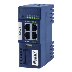
Ewon Cosy+ Ethernet router
705,43 EUR Incl. VAT

360 W 24 VDC / 15 A UPS backup power supply Bicker with LiFePO4 battery and USB-C + RS485 Modbus interfaces
716,32 EUR Incl. VAT

Training PROFINET – Basics, Diagnostics & Network Troubleshooting, 2 days
1 076,90 EUR Incl. VAT
Diagnostics, troubleshooting and monitoring of PROFINET Networks
from 367,84 EUR Incl. VAT

ProfiTrace 2 Ultra Plus – PROFIBUS DP Tester
4 399,56 EUR Incl. VAT
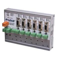
ProfiHub B5+R PROFIBUS multi-repeater
1 724,25 EUR Incl. VAT
Related products7
auto.spy - software for diagnostics of SIMATIC S7-300/-400/-1200/-1500 and S5 PLCs, OPC UA/DA data and camera recordings
from 713,90 EUR Incl. VAT
Ewon Cosy+ Ethernet router
705,43 EUR Incl. VAT
360 W 24 VDC / 15 A UPS backup power supply Bicker with LiFePO4 battery and USB-C + RS485 Modbus interfaces
716,32 EUR Incl. VAT
Training PROFINET – Basics, Diagnostics & Network Troubleshooting, 2 days
1 076,90 EUR Incl. VAT
Diagnostics, troubleshooting and monitoring of PROFINET Networks
from 367,84 EUR Incl. VAT
ProfiTrace 2 Ultra Plus – PROFIBUS DP Tester
4 399,56 EUR Incl. VAT
ProfiHub B5+R PROFIBUS multi-repeater
1 724,25 EUR Incl. VAT