

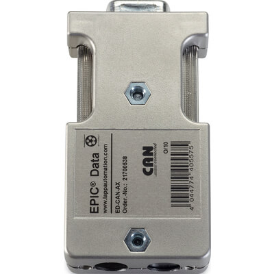
LAPP 21700538 - 180° CAN / CANopen connector

LAPP 21700538 ED-CAN-AX: CAN / CANopen connector, 9-pin D-Sub, 180° outlet, without PG port. Screw terminals, switchable 120 Ω termination, IP20. More
Code: 21700538
LAPP 21700538 ED-CAN-AX: CAN / CANopen connector, 9-pin D-Sub, 180° outlet, without PG port. Screw terminals, switchable 120 Ω termination, IP20. More
Code: 21700538
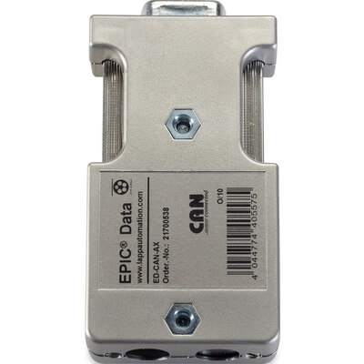
EPIC® DATA CAN Sub-D
180° CAN / CANopen connector
No PG port
The LAPP 21700538 ED-CAN-AX connects a CAN/CANopen cable to a device with a 9-pin D-Sub interface. The 180° cable outlet, screw terminals and metallised housing facilitate installation in a control cabinet. The integrated 120 Ω terminator can be switched between the ‘OFF’ through-connection mode and the ‘ON’ terminating mode. This version does not have an additional PG port.
Please send us the port designation, cable diameter and the required version. We will check that the connector and accessories are correct.
Device connections and bespoke cabling
This connector is used when constructing, modifying or maintaining a CAN / CANopen bus network. Connecting the wires using screw terminals does not require a special crimping tool. When selecting a connector, check the device interface, the cable exit point and access to the termination switch.
OFF / ON switch and disconnection of the outgoing bus
Inside the through bus, the switch must be set to the OFF position. At the physical end of the line, set the switch to ON to connect a 120 Ω terminator. The ON position also disconnects the outgoing bus. If you switch it on in the middle of the route, you will cut off the connected devices.
Terminate the copper CAN bus at both physical ends according to the network design, usually with a 120 Ω resistor between CAN_H and CAN_L. Device addresses do not determine the end of the cable run. CAN termination does not use the power supply circuit of a PROFIBUS termination network.
Wiring of D-Sub cables and contacts
Connect the cable to the 6 screw terminals for conductors up to 1.0 mm². The connector accepts cables with an outer diameter of 5-8 mm. CAN Low goes to pin 2, CAN High to pin 7 and CAN Gnd to pin 3. Check that the polarity is correct, that the shield is properly connected and that the cable is mechanically strain-relieved.
| Pin 2 | CAN Low |
|---|---|
| Pin 7 | CAN High |
| Pin 3 | CAN Gnd |
Power supply for other network components
The ED-CAN-AX straight version does not have a separate power supply connection for other network components, unlike the angled variants ED-CAN-90 and ED-CAN-90-PG. Do not connect power from a different type of connector here without first checking the wiring.
Access for programming and diagnostics
This order code does not include an additional PG port. If you require access for programming or diagnostics via a second D-Sub interface, please select variant 21700536 ED-CAN-90-PG.
This product is designed for CAN and CANopen. For use in other CAN-based networks, such as DeviceNet, please check the pin-out, power supply and device requirements. The CAN designation does not imply universal interchangeability of all connectors or support for CAN FD at higher data rates.
Technical specifications 21700538
| Manufacturer | LAPP |
|---|---|
| Order number | 21700538 |
| Series | EPIC® DATA CAN Sub-D |
| Model designation | ED-CAN-AX |
| Device interfaces | 9-pin D-Sub, female |
| Cable outlet | 180° |
| PG / diagnostic port | No |
| Connecting the cable | 6 screw terminals, conductors up to 1.0 mm² |
| Cable diameter | 5-8 mm |
| Case | Metallised, EMC protection |
| Uses | CAN / CANopen |
| Maximum transfer speed | 1 Mbit/s |
| Termination | 120 Ω, switchable |
| OFF position | Through-wiring, terminations disabled |
| ON position | Termination enabled, outgoing bus disconnected |
| Power connections for other components | Not in the straight version |
| Protection rating | IP20 |
| Operating temperature | 0 to +60 °C |
| Storage and transport | -25 to +75 °C |
| Dimensions | 67.5 × 35 × 17 mm |
| Net catalogue weight | 47 g |
Connectors and installation accessories
We will supply the LAPP 21700538 connector. We will select the CAN/CANopen cable, tools, mating connector and any diagnostic adaptor separately, depending on the installation. We will confirm the quantity and contents of the package in the quotation.
Selecting and connecting the connector
When should the termination switch be set to the ON position?
Inside the through bus, the switch must be set to the OFF position. At the physical end of the line, set the switch to ON to connect a 120 Ω terminator. The ON position also disconnects the outgoing bus. If you switch it on in the middle of the route, you will cut off the connected devices.
Does the ON position disconnect downstream devices from the bus?
Inside the through bus, the switch must be set to the OFF position. At the physical end of the line, set the switch to ON to connect a 120 Ω terminator. The ON position also disconnects the outgoing bus. If you switch it on in the middle of the route, you will cut off the connected devices.
What is the difference between 21700537, 21700536 and 21700538?
21700537 ED-CAN-90 has a 90° outlet without a PG port. 21700536 ED-CAN-90-PG has a 90° outlet and a PG port. 21700538 ED-CAN-AX has a straight 180° outlet without a PG port. The angled versions have separate power connections; the straight version does not.
Does this connector have a PG port?
This order code does not include an additional PG port. If you require access for programming or diagnostics via a second D-Sub interface, please select variant 21700536 ED-CAN-90-PG.
What types of wires and cables can be connected?
Connect the cable to the 6 screw terminals for conductors up to 1.0 mm². The connector accepts cables with an outer diameter of 5-8 mm. CAN Low goes to pin 2, CAN High to pin 7 and CAN Gnd to pin 3. Check that the polarity is correct, that the shield is properly connected and that the cable is mechanically strain-relieved.
Why order from FOXON
We can help you match the choice of connector to the actual CAN network wiring. Please send us a photograph of the port and cable, the device model number, and a brief description of your requirements.
Precise connector design
We will check the order code, the device interface and the available space for the cable.
Cables and accessories
We will select the appropriate cable, connector and any necessary fittings.
Checking the wiring
We’ll go through the pinout, the shielding connections and the termination of the cable run.
CAN network diagnostics
We can help you choose a tester or identify the causes of communication failures.
Czech technical support
We will discuss the specific equipment, topology and procedure for replacing the connector.
Delivery Confirmation
Before placing an order, we will confirm the design, the quantity and the delivery date.
LAPP documentation and installation guides
In the ‘Downloads’ tab, you will find the current LAPP technical data sheet for the exact order number 21700538. The accompanying installation instructions explain the OFF/ON function. An EU Declaration of Conformity for this range is also available.
Open downloadsTechnical specifications 21700538
ED-CAN-AX
Interfaces and installation
| Manufacturer | LAPP |
|---|---|
| Order number | 21700538 |
| Series | EPIC® DATA CAN Sub-D |
| Model designation | ED-CAN-AX |
| Device interfaces | 9-pin D-Sub, female |
| Cable outlet | 180° |
| PG / diagnostic port | No |
| Connecting the cable | 6 screw terminals, conductors up to 1.0 mm² |
| Cable diameter | 5-8 mm |
| Case | Metallised, EMC protection |
Communication and termination
| Uses | CAN / CANopen |
|---|---|
| Maximum transfer speed | 1 Mbit/s |
| Termination | 120 Ω, switchable |
| OFF position | Through-wiring, terminations disabled |
| ON position | Termination enabled, outgoing bus disconnected |
| Power connections for other components | Not in the straight version |
Operating conditions
| Protection rating | IP20 |
|---|---|
| Operating temperature | 0 to +60 °C |
| Storage and transport | -25 to +75 °C |
| Dimensions | 67.5 × 35 × 17 mm |
| Net catalogue weight | 47 g |
Connection and installation
Connect the cable to the 6 screw terminals for conductors up to 1.0 mm². The connector accepts cables with an outer diameter of 5-8 mm. CAN Low goes to pin 2, CAN High to pin 7 and CAN Gnd to pin 3. Check that the polarity is correct, that the shield is properly connected and that the cable is mechanically strain-relieved.
The ED-CAN-AX straight version does not have a separate power supply connection for other network components, unlike the angled variants ED-CAN-90 and ED-CAN-90-PG. Do not connect power from a different type of connector here without first checking the wiring.
Operating conditions and termination
Inside the through bus, the switch must be set to the OFF position. At the physical end of the line, set the switch to ON to connect a 120 Ω terminator. The ON position also disconnects the outgoing bus. If you switch it on in the middle of the route, you will cut off the connected devices.
Terminate the copper CAN bus at both physical ends according to the network design, usually with a 120 Ω resistor between CAN_H and CAN_L. Device addresses do not determine the end of the cable run. CAN termination does not use the power supply circuit of a PROFIBUS termination network.
Choosing the right connector
When should the termination switch be set to the ON position?
Inside the through bus, the switch must be set to the OFF position. At the physical end of the line, set the switch to ON to connect a 120 Ω terminator. The ON position also disconnects the outgoing bus. If you switch it on in the middle of the route, you will cut off the connected devices.
Does the ON position disconnect downstream devices from the bus?
Inside the through bus, the switch must be set to the OFF position. At the physical end of the line, set the switch to ON to connect a 120 Ω terminator. The ON position also disconnects the outgoing bus. If you switch it on in the middle of the route, you will cut off the connected devices.
What is the difference between 21700537, 21700536 and 21700538?
21700537 ED-CAN-90 has a 90° outlet without a PG port. 21700536 ED-CAN-90-PG has a 90° outlet and a PG port. 21700538 ED-CAN-AX has a straight 180° outlet without a PG port. The angled versions have separate power connections; the straight version does not.
Installation and connection
Does this connector have a PG port?
This order code does not include an additional PG port. If you require access for programming or diagnostics via a second D-Sub interface, please select variant 21700536 ED-CAN-90-PG.
What types of wires and cables can be connected?
Connect the cable to the 6 screw terminals for conductors up to 1.0 mm². The connector accepts cables with an outer diameter of 5-8 mm. CAN Low goes to pin 2, CAN High to pin 7 and CAN Gnd to pin 3. Check that the polarity is correct, that the shield is properly connected and that the cable is mechanically strain-relieved.
How do you connect CAN Low and CAN High?
Connect the cable to the 6 screw terminals for conductors up to 1.0 mm². The connector accepts cables with an outer diameter of 5-8 mm. CAN Low goes to pin 2, CAN High to pin 7 and CAN Gnd to pin 3. Check that the polarity is correct, that the shield is properly connected and that the cable is mechanically strain-relieved.
How does the power connection work?
The ED-CAN-AX straight version does not have a separate power supply connection for other network components, unlike the angled variants ED-CAN-90 and ED-CAN-90-PG. Do not connect power from a different type of connector here without first checking the wiring.
Operation and Diagnostics
Is this connector compatible with both DeviceNet and CAN FD?
This product is designed for CAN and CANopen. For use in other CAN-based networks, such as DeviceNet, please check the pin-out, power supply and device requirements. The CAN designation does not imply universal interchangeability of all connectors or support for CAN FD at higher data rates.
Do I need a PLC or EDS configuration?
A passive connector has no address, firmware or EDS file of its own. Simply connecting the connector does not require any changes to the PLC programme. However, if you make any alterations to the cabling, check the topology and how the system responds to a station being disconnected.
Why did the network stop communicating after being switched to ON?
The ON position disconnects the output bus. If the connector is inside the cable, switch it back to OFF in accordance with the network design. At the same time, check that both actual ends of the cable are correctly terminated and that the CAN Low and CAN High signals have not been swapped.
Highlighted items are mandatory.