

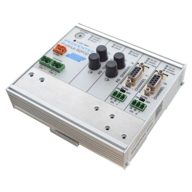
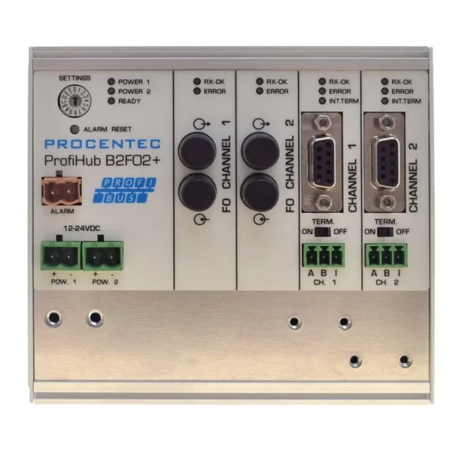
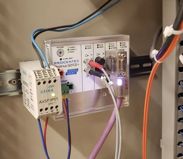


ProfiHub B2FO2+ fiber MM coupler PROFIBUS

The ProfiHub B2FO2+ multi repeater allows you to create up to 2 metallic segments, connected via a fibre optic network. It is an ideal solution for connecting remote PROFIBUS metallic nests through fibre optics. The ProfiHub B2FO2+ will make your network more robust and reliable. It is suitable for deployment in new as well as existing PROFIBUS DP networks. Not compatible with ring topology. More
Code: 17220
The ProfiHub B2FO2+ multi repeater allows you to create up to 2 metallic segments, connected via a fibre optic network. It is an ideal solution for connecting remote PROFIBUS metallic nests through fibre optics. The ProfiHub B2FO2+ will make your network more robust and reliable. It is suitable for deployment in new as well as existing PROFIBUS DP networks. Not compatible with ring topology. More
Code: 17220
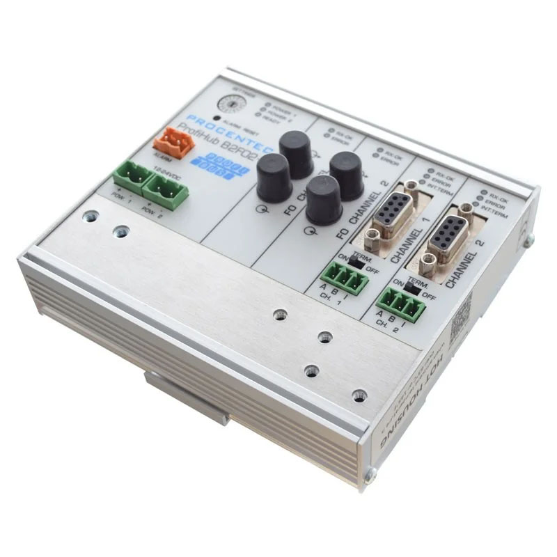
ProfiHub B2FO2+ · 17220
ProfiHub B2FO2+
Two optical channels at 850 nm and 2 isolated RS485 segments
The ProfiHub B2FO2+ 17220 connects the PROFIBUS DP optical backbone to two local metallic segments. It combines an optical converter and galvanically isolated RS485 repeaters in a single unit. Two optical channels enable line, star or tree topologies.
Please send us the topology, network speed and number of stations. We will check the connections and required accessories.
Better signal quality and longer PROFIBUS network operation
By dividing a long cable run into shorter sections, you will improve signal transmission conditions and make maintenance easier. Minimising downtime caused by poor signal quality helps to extend the operational life of your existing PROFIBUS network. Plan the installation during a shutdown and, once the connection has been made, check both communication and signal quality.
A repeater regenerates the signal and provides galvanic isolation between individual metallic segments. It helps to limit the propagation of electrical faults and interference between them. Proper shielding, bonding and termination remain essential. A faulty cable or connector must be repaired; splitting the network does not replace rectifying the cause of the fault.
Use in both new and existing networks
For connecting remote switchboards via an optical backbone and linking 2 local segments to peripherals, actuators or measuring instruments. The optical link helps to isolate remote parts of the facility without the need for a conductive data cable connection.
Plan the replacement or installation of equipment in accordance with the technology’s operational requirements. Once connected, check the polarity, power supply, termination and response of the connected stations.
Optical backbone and local segments
Each metallic channel has its own powered termination and a DB9 connector for connection to a bus or analyser. The DB9 and the terminal block for the same channel belong to a single electrical segment.
The two optical channels each have a transmitter and a receiver, giving four ST/BFOC connectors in total. Match the TX/RX wiring to the other device and check its operating mode when designing the connection.


850 nm and fibre selection
Use 50/125 µm or 62.5/125 µm multimode fibre. Provided the optical budget is met, the reach is up to 3 km per link and is independent of the transmission speed. For PCF/HCS 200/230 µm, the range is up to 200 m.
Length alone is not enough: check the attenuation of the cable, splices and connectors, and the parameters of both optical ends. Compatibility with a specific OLM requires the same wavelength, fibre, connector and transmission mode.
Optical line and metallic redundancy
The ProfiHub B2FO2+ supports point-to-point, line, star or tree optical connections. Do not use it as a converter for a redundant optical ring. For a ring configuration, select the appropriate FOR family with compatible optics.
Cable redundancy is a different feature: in the +R version, CH1 and CH2 form a single redundant metallic pair. Do not confuse this with optical channel redundancy.
Diagnostics and differences between hardware configurations
The DP-V0 diagnostic slave is a function of the +RD diagnostic version. It uses the GSD file PROC6972.gsd, with a default address of 126 and a maximum of 85 bytes of inputs and 5 bytes of outputs. Please check the availability of the +R/+RD functions for a specific unit by referring to the label, serial number and delivery configuration.
Once activated and configured, the diagnostic slave provides status information and statistics for the PLC, DCS and the ComBricks PROFIBUS network analyser. To read the diagnostic data in the PLC, you will need to install a GSD and implement data processing. The device does not have its own Ethernet web interface.
Newer +R models with a serial number starting with 19 or higher use automatic speed detection; a change in operating mode takes effect without the need to restart. Older units have different position assignments, including a fixed speed. Do not carry over the settings between hardware revisions.
Power supply, alarm and timing
The rated supply voltage is 12 to 24 V DC; the two inputs allow for power redundancy. The current draw at full load is 300 mA. For true redundancy, use two independent power supplies.
The potential-free contact has a limit of 24 V DC / 0.5 A. It reports the power supply status, redundant paths and configured events, depending on the version.
Optical links, cascading and Robust Repeating increase latency. Recalculate Tslot and MinTSDR for the actual fibre length and number of modules. Standard transparent repeating does not require any changes to the PLC programme; special modes and diagnostics have additional requirements.

Cable length depending on the segment speed
Up to 31 additional devices, including hubs, optical converters and analysers, can be connected to each metallic channel. Please ensure that the cable length is appropriate for the speed and segment load, and that the cables are correctly terminated.
| 9.6 / 19.2 / 45.45 / 93.75 kbit/s | 1200 m |
|---|---|
| 187.5 kbit/s | 1000 m |
| 500 kbit/s | 400 m |
| 1.5 Mbit/s | 200 m |
| 3 / 6 / 12 Mbit/s | 100 m |
Where the topology allows, we recommend smaller groups, for example of 5 to 10 stations per machine or switchboard. This is a FOXON recommendation to make maintenance more manageable, not a technical limitation of the equipment.
The number of devices in the cascade is limited by the master’s timing and the total delay. When designing the system, check the speed, operating mode and bus parameters. A larger number of repeaters does not mean an unlimited network length.
Segments and correct termination
A segment is a section of the network in which the electrical signal is the same. Each metallic segment must be properly terminated at both ends with a termination resistor that is switched on and powered. Adjust the termination settings to suit the actual topology; do not use two terminations at the same point.
Each segment has its own electrical specifications. During maintenance, the power supply and terminations of the segments that are to continue communicating must remain intact. The response to a missing peripheral is also determined by the PLC’s configuration and programme.
PLC configuration and commissioning
In normal transparent mode, the repeater does not require its own PROFIBUS address or any changes to the PLC programme. However, please check the bus timing and the control system’s response to the disconnection of peripherals. Diagnostic slave and special operating modes have their own configuration requirements.
ProfiHub B2FO2+, order number 17220
| Order number | 17220 |
|---|---|
| Metallic segments | 2 galvanically isolated RS485 channels |
| Optical channels | Two optical channels, four ST/BFOC connectors |
| Speed | 9.6 kbit/s to 12 Mbit/s, including 45.45 kbit/s |
| Speed detection | Automatic; fixed speed only for compatible older versions |
| Supported protocols | DP-V0 / DP-V1 / DP-V2, FDL, MPI, FMS, PROFIsafe and PROFIdrive; transparent physical-layer transmission does not replace the safety assessment of the application. |
| Devices per copper channel | Up to 31 additional devices |
| Cable redundancy | In the +R version: CH1 and CH2 form a single pair |
| Wavelength | 850 nm |
| Fibre type | MM 50/125 µm, MM 62.5/125 µm or PCF/HCS 200/230 µm |
| MM link range | Up to 3 km per link, provided the optical budget is met |
| PCF/HCS coverage | Up to 200 m per connection |
| Optical topology | Point-to-point, line, star and tree |
| Redundant optical ring | No |
| Diagnostic slave | Diagnostic version only +RD, GSD PROC6972.gsd |
| Diagnostic slave address | Default 126, software-configurable |
| Diagnostic data | Max. 85 bytes of input and 5 bytes of output |
| Power supply | Rated 12-24 V DC, two inputs; absolute voltage limits 9-31 V DC |
| Current consumption | 300 mA at full channel load |
| Alarm contact | Potential-free, max. 24 V DC / 0.5 A |
| Protection rating | IP20 |
| Operating temperature | -25 to +70 °C |
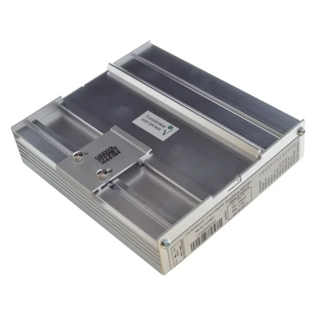
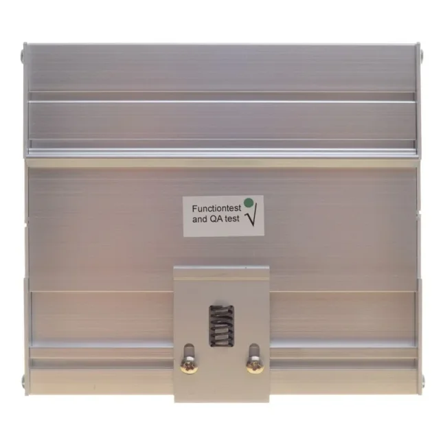
| Installation | DIN rail 35 × 7.5 mm |
| Dimensions | 129 × 113 × 43 mm; please check the space for connectors before delivery |
| Net catalogue weight | 592 g |
When installing, leave space for the connectors, cable bends and access to the controls. We will confirm the design and dimensions based on the specific delivery.
Module and installation accessories
We will supply the ProfiHub B2FO2+ 17220. We will confirm the contents of the included connectors, terminal blocks and mounting parts in the quotation. We will select the power supply, cables, fibre optic patch cords and analysers according to the specific network and equipment configuration.
Selection and commissioning
How many segments does this model offer?
The ProfiHub B2FO2+ has 2 RS485 metallic segments and two optical channels. The DB9 connector and the terminal block for the same metallic channel do not constitute additional separate segments.
Is it possible to create a redundant optical ring?
No. Two optical channels do not imply support for ring redundancy. For a redundant ring, select a compatible FOR family and check its wavelength and fibre type.
Which fibre type and cable length can I use?
For MM 50/125 µm or 62.5/125 µm, the reach is up to 3 km per link, provided the optical budget is met. For PCF/HCS 200/230 µm, it is up to 200 m. The optics operate at 850 nm.
Is this device a direct replacement for any Siemens OLM?
No. Check the exact OLM type, wavelength, fibre type, connector and operating mode. The fact that the ST/BFOC connector is the same does not in itself guarantee compatibility.
What does ‘metallic redundancy’ mean?
In the +R configuration, CH1 and CH2 form a single redundant cable pair between compatible devices. This is a metallic function which does not replace a redundant optical ring.
Does every unit have a built-in diagnostic slave?
The DP-V0 diagnostic slave is a function of the +RD diagnostic version. It uses the GSD file PROC6972.gsd, with a default address of 126 and a maximum of 85 bytes of inputs and 5 bytes of outputs. Please check the availability of the +R/+RD functions for a specific unit by referring to the label, serial number and delivery configuration.
Why order from FOXON
We have been an official distributor for HMS Anybus (formerly PROCENTEC) since 2007.
Proposed network layout
We will review the network speed, cable lengths, number of stations and control cabinet locations. We will propose separate segments to suit the installation.
Selecting accessories
We will select the cabling, PROFIBUS connectors and power supply. We will check the termination of the individual segments.
Verification of a specific design
Before ordering, we will check the product order number, required functions and hardware revision.
Measurement and maintenance
We can help you distinguish between a physical layer problem and a communication error, and select the appropriate diagnostic tool.
Czech technical support
We will discuss specific wiring configurations, fault symptoms and options for long-term network monitoring.
Delivery in accordance with the project
Before placing an order, we will confirm the availability of the specific model, the quantity and the delivery date.
Manuals and technical documentation
In the ‘Downloads’ tab, you will find the technical data sheet, manual and declaration of conformity. Please use the GSD files only for the relevant diagnostic version. For older units, please check the serial number and ensure the settings are correct.
Open downloadsTechnical specifications of the ProfiHub B2FO2+
Order number 17220. Please refer to the specific model of the device for its specifications and functions.
Interfaces and transmission
| Order number | 17220 |
|---|---|
| Metallic segments | 2 galvanically isolated RS485 channels |
| Optical channels | Two optical channels, four ST/BFOC connectors |
| Speed | 9.6 kbit/s to 12 Mbit/s, including 45.45 kbit/s |
| Speed detection | Automatic; fixed speed only for compatible older versions |
| Supported protocols | DP-V0 / DP-V1 / DP-V2, FDL, MPI, FMS, PROFIsafe and PROFIdrive; transparent physical-layer transmission does not replace the safety assessment of the application. |
| Devices per copper channel | Up to 31 additional devices |
| Cable redundancy | In the +R version: CH1 and CH2 form a single pair |
Optical parameters
| Wavelength | 850 nm |
|---|---|
| Fibre type | MM 50/125 µm, MM 62.5/125 µm or PCF/HCS 200/230 µm |
| MM link range | Up to 3 km per link, provided the optical budget is met |
| PCF/HCS coverage | Up to 200 m per connection |
| Optical topology | Point-to-point, line, star and tree |
| Redundant optical ring | No |
Diagnostics and Power Supply
| Diagnostic slave | Diagnostic version only +RD, GSD PROC6972.gsd |
|---|---|
| Diagnostic slave address | Default 126, software-configurable |
| Diagnostic data | Max. 85 bytes of input and 5 bytes of output |
| Power supply | Rated 12-24 V DC, two inputs; absolute voltage limits 9-31 V DC |
| Current consumption | 300 mA at full channel load |
| Alarm contact | Potential-free, max. 24 V DC / 0.5 A |
Mechanical design
| Protection rating | IP20 |
|---|---|
| Operating temperature | -25 to +70 °C |
| Installation | DIN rail 35 × 7.5 mm |
| Dimensions | 129 × 113 × 43 mm; please check the space for connectors before delivery |
| Net catalogue weight | 592 g |
Length of the metallic segment as a function of speed
| 9.6 / 19.2 / 45.45 / 93.75 kbit/s | 1200 m |
|---|---|
| 187.5 kbit/s | 1000 m |
| 500 kbit/s | 400 m |
| 1.5 Mbit/s | 200 m |
| 3 / 6 / 12 Mbit/s | 100 m |
Where the topology allows, we recommend smaller groups, for example of 5 to 10 stations per machine or switchboard. This is a FOXON recommendation to make maintenance more manageable, not a technical limitation of the equipment.
The number of devices in the cascade is limited by the master’s timing and the total delay. When designing the system, check the speed, operating mode and bus parameters. A larger number of repeaters does not mean an unlimited network length.
Termination and operating conditions
A segment is a section of the network in which the electrical signal is the same. Each metallic segment must be properly terminated at both ends with a termination resistor that is switched on and powered. Adjust the termination settings to suit the actual topology; do not use two terminations at the same point.
Before changing the operating mode, please check the relevant manual and version. We can help you check the label and accessories for the parameters of a specific delivery.
Frequently Asked Questions about ProfiHub B2FO2+
Selection, connection, diagnostics and operating conditions.
Selection and use
How many segments does this model offer?
The ProfiHub B2FO2+ has 2 RS485 metallic segments and two optical channels. The DB9 connector and the terminal block for the same metallic channel do not constitute additional separate segments.
Is it possible to create a redundant optical ring?
No. Two optical channels do not imply support for ring redundancy. For a redundant ring, select a compatible FOR family and check its wavelength and fibre type.
Which fibre type and cable length can I use?
For MM 50/125 µm or 62.5/125 µm, the reach is up to 3 km per link, provided the optical budget is met. For PCF/HCS 200/230 µm, it is up to 200 m. The optics operate at 850 nm.
Is this device a direct replacement for any Siemens OLM?
No. Check the exact OLM type, wavelength, fibre type, connector and operating mode. The fact that the ST/BFOC connector is the same does not in itself guarantee compatibility.
Wiring and diagnostics
What does ‘metallic redundancy’ mean?
In the +R configuration, CH1 and CH2 form a single redundant cable pair between compatible devices. This is a metallic function which does not replace a redundant optical ring.
Does every unit have a built-in diagnostic slave?
The DP-V0 diagnostic slave is a function of the +RD diagnostic version. It uses the GSD file PROC6972.gsd, with a default address of 126 and a maximum of 85 bytes of inputs and 5 bytes of outputs. Please check the availability of the +R/+RD functions for a specific unit by referring to the label, serial number and delivery configuration.
Can the diagnostics be viewed in ComBricks?
Yes, provided the appropriate diagnostic configuration has been activated and set up. The PLC/DCS and the ComBricks continuous analyser both read the status and statistics. The web-based overview is provided by a separate ComBricks unit; the instrument itself does not have its own Ethernet web interface.
Can the transmission speed be set to a fixed value?
It depends on the revision. Newer +R models with a serial number starting with 19 or higher use automatic detection and different position assignments to older models. Always select the settings according to the specific label and manual.
Network operations
Do I need to change the PLC programme?
In normal transparent mode, the repeater does not require its own PROFIBUS address or any changes to the PLC programme. However, please check the bus timing and the control system’s response to the disconnection of peripherals. Diagnostic slave and special operating modes have their own configuration requirements.
How should copper segments be terminated?
A segment is a section of the network in which the electrical signal is the same. Each metallic segment must be properly terminated at both ends with a termination resistor that is switched on and powered. Adjust the termination settings to suit the actual topology; do not use two terminations at the same point.
How many devices can be connected?
Up to 31 additional devices, including hubs, optical converters and analysers, can be connected to each metallic channel. Please ensure that the cable length is appropriate for the speed and segment load, and that the cables are correctly terminated.
Can multiple optical converters be connected in a cascade?
The number of devices in the cascade is limited by the master’s timing and the total delay. When designing the system, check the speed, operating mode and bus parameters. A larger number of repeaters does not mean an unlimited network length.
Highlighted items are mandatory.

Training PROFIBUS - Basics, Diagnostics & Network Troubleshooting, 2 days
1 076,90 EUR Incl. VAT
Related products1
Training PROFIBUS - Basics, Diagnostics & Network Troubleshooting, 2 days
1 076,90 EUR Incl. VAT