

96 W 24 VDC / 4 A Bicker UPS with Li-Ion battery


96 W 24 VDC / 4 A Bicker UPS with Li-Ion battery

Intelligent industrial 24 VDC / 4 A, 96 W DC UPS with integrated Li-Ion battery, USB and RS232 communication, controlled PC shutdown and restart, and DIN rail mounting. More
Code: UPSI-2406DP1
Intelligent industrial 24 VDC / 4 A, 96 W DC UPS with integrated Li-Ion battery, USB and RS232 communication, controlled PC shutdown and restart, and DIN rail mounting. More
Code: UPSI-2406DP1
Bicker UPSI-2406DP1 · Li-Ion battery backup power supply
Keep your 24 V devices running even during an extended power failure
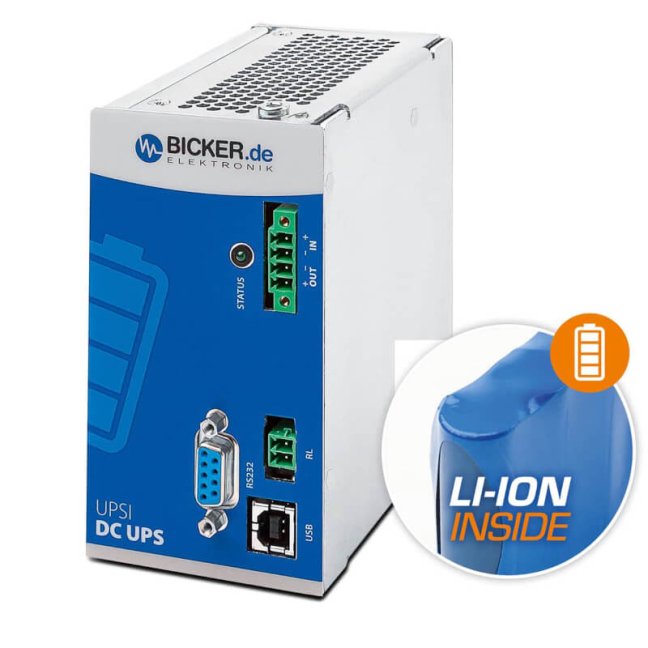
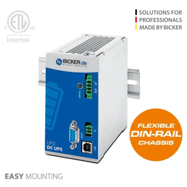
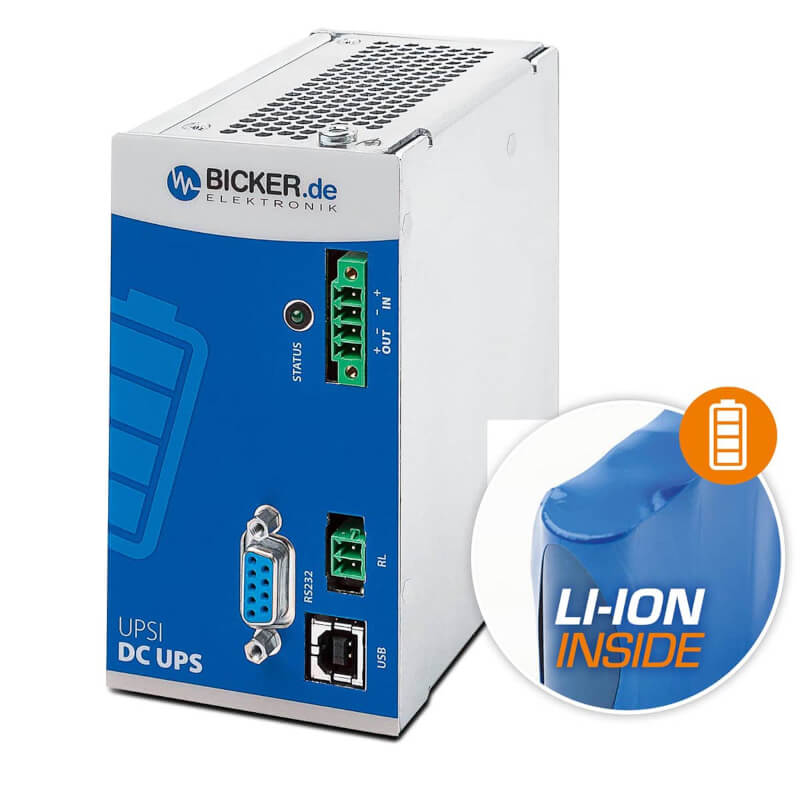
The Bicker UPSI-2406DP1 is an industrial DC UPS backup power supply for equipment powered by 24 VDC. It offers a nominal power of 96 W and a current of 4 A. The integrated Li-Ion battery with a capacity of 37 Wh provides approximately 12 minutes of backup time at a current draw of 4 A. This gives an industrial computer, machine controller, network devices, or measuring equipment time to bridge the outage or safely save data and shut down. The compact UPS is mounted on a DIN rail in a control cabinet.
How long do you need to keep your equipment running during a power failure?
Tell us which devices you want to back up and for how long. If you know their power consumption in watts, include it; we will help you select a suitable backup power supply and power supply unit.
Reliable backup power for industrial automation
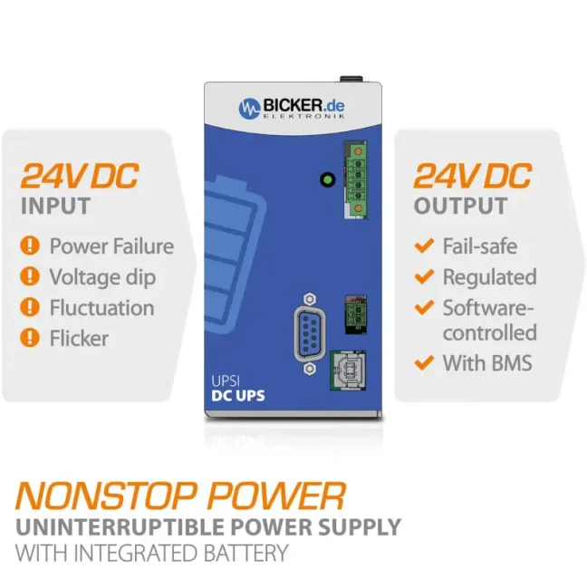
A UPS backup power supply helps protect industrial computers, machine controllers (PLCs), network devices, measuring equipment, and other 24 V devices against power failures and voltage dips. The UPSI-2406DP1 switches to the integrated Li-Ion battery in less than 600 µs, or 0.6 milliseconds, when the input voltage is lost. In backup mode, it regulates the output to 23.5 VDC.
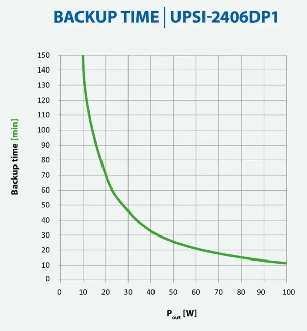
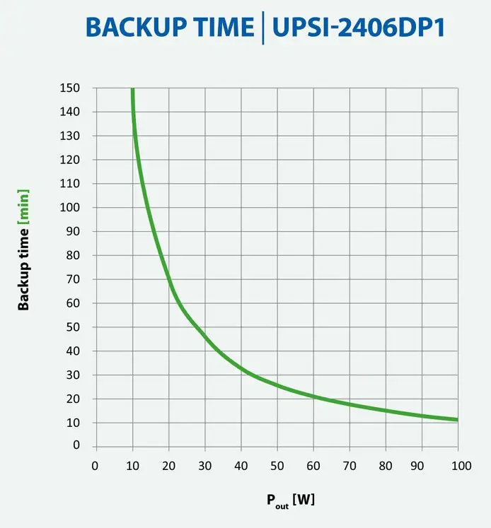
The integrated 37 Wh battery provides approximately 12 minutes of backup time at the nominal current of 4 A under reference conditions. Backup time increases at lower current draw.
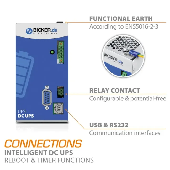
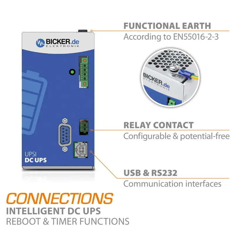
USB Type B enables communication with a computer. RS232 and a potential-free relay contact are also available for power-failure signalling or status transfer to another system.
The UPS can warn a computer about a power failure, initiate a controlled shutdown, and enable automatic restart after power returns. Settings can be adjusted for the specific application.
For new control cabinets and upgrades to existing equipment
The UPSI-2406DP1 can be used when building a new control cabinet or adding backup power to an existing machine. It helps protect equipment powered by 24 V against power failures, voltage dips, and other power disturbances.
A machine controller, industrial computer, industrial Ethernet switch, measuring instrument, or other electronics can therefore continue operating or shut down safely. DIN rail mounting according to EN 60715 makes installation directly in a control cabinet easy.

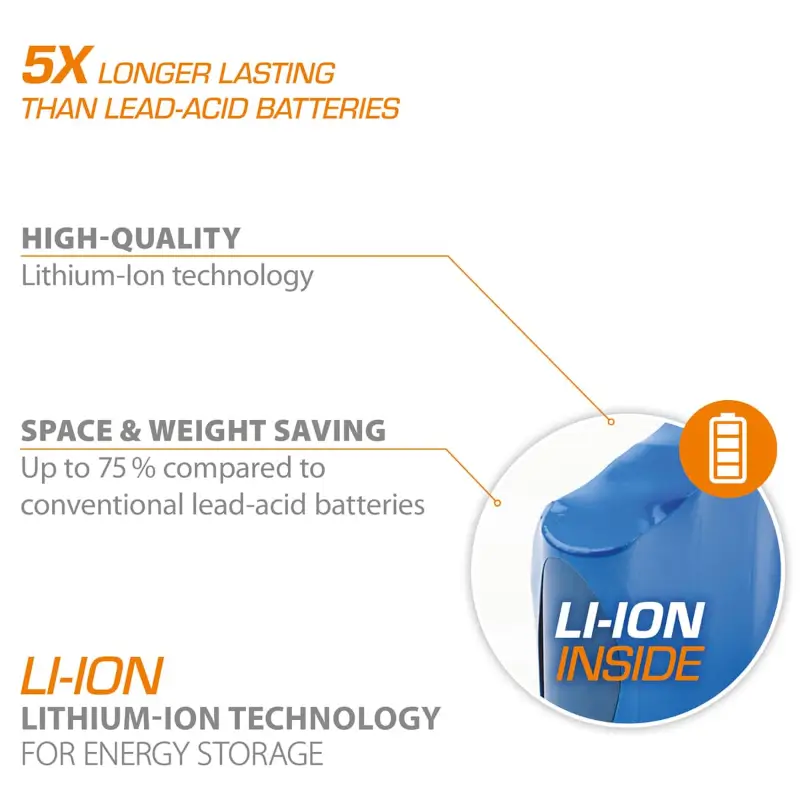
37 Wh Li-Ion battery for longer backup time
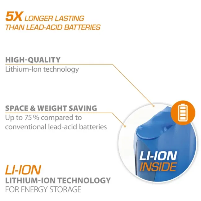
The UPSI-2406DP1 has an integrated lithium-ion battery with a nominal capacity of 2.5 Ah / 37 Wh. Compared with supercapacitor versions, it is intended primarily for applications where equipment must remain in operation for several minutes during a power failure, rather than only several tens of seconds.
At a current draw of 4 A, the manufacturer specifies approximately 12 minutes of backup time. The actual time depends on the load, battery condition and age, and operating temperature. The battery has a nominal voltage of 14.8 V, while the UPS electronics provide controlled CC/CV/CP charging and protection against excessive discharge.
How long will equipment remain operational during a power failure?
At the nominal output current of 4 A, the UPSI-2406DP1 provides approximately 12 minutes of backup time. At lower current draw, the time increases significantly. The manufacturer provides backup characteristics based on both the current and power of the connected equipment.
For system design, add up the power consumption of all devices that must remain powered during an outage. Also allow for a reserve, because the actual time is affected by temperature, battery age, and its current state of charge.
View UPS status and settings in software
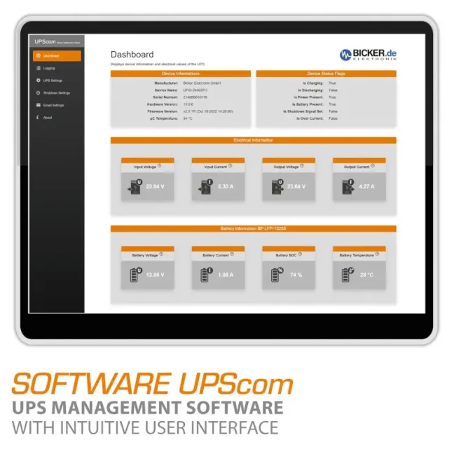
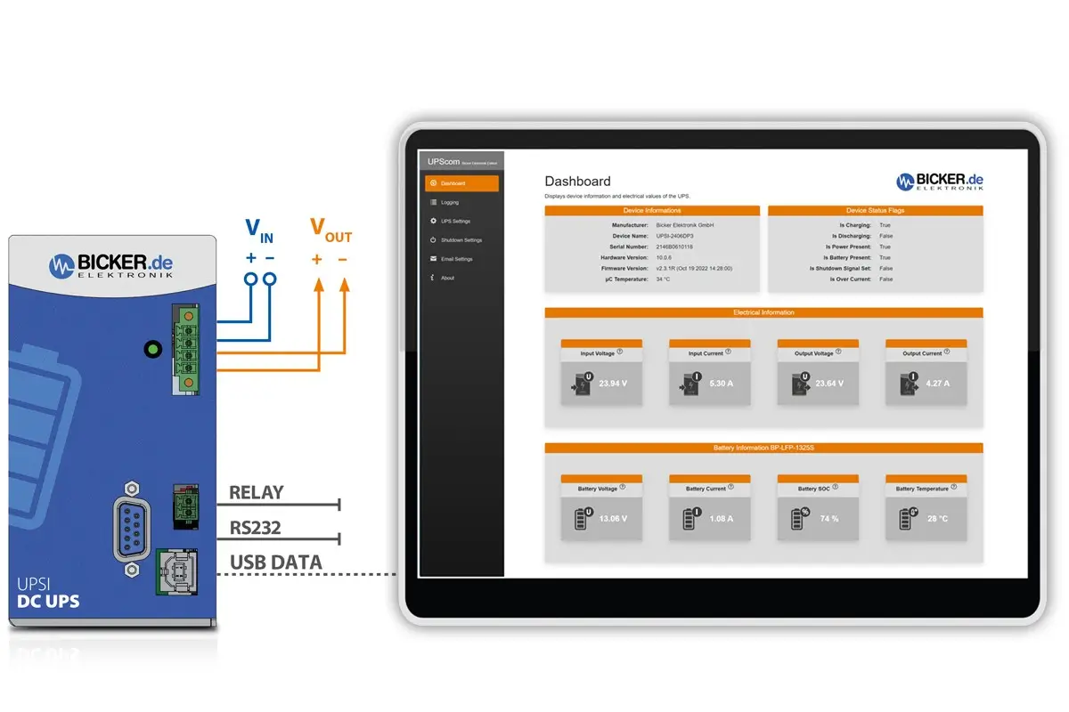
The UPSI-2406DP1 supports UPScom software for Windows and Linux. It enables monitoring of UPS and battery status, response to power failures, and control of connected-computer shutdown.
Operating parameters of the UPS can be configured and the state of charge monitored via USB. Supported operating systems can recognize the device via USB as a UPS through the HID interface.
- monitoring of battery status and current operating status,
- setting of shutdown delay and maximum backup time,
- setting of the minimum battery capacity before output startup,
- detection of load reduction below a configured threshold,
- control of safe computer shutdown,
- automatic restart after power returns,
- ability to run custom actions or scripts before shutdown.
Safe computer shutdown and automatic restart
When input power fails, the UPS can signal the condition to a connected industrial computer. The computer then has time to save data, close running applications, and safely shut down the operating system.
After power returns, the Reboot function can be used to automatically restore operation. This is especially practical for unattended industrial computers and remote installations, where the device would otherwise need to be physically restarted. This function must also be coordinated with the computer's BIOS and operating-system settings.
USB Type B and the RS232 serial interface are available for communication. The UPS can also transmit power-failure status through a potential-free relay contact.
Connection to a computer, machine, and power-failure signalling
Practical functions for real-world operation
The UPSI-2406DP1 continuously monitors the status of the power supply, battery, and connected load. Depending on the settings, it can bridge the entire power failure or provide sufficient time for the equipment to shut down safely.
At maximum charging power, charging the integrated Li-Ion battery takes approximately 55 minutes. The actual time depends on the input voltage, power draw of the connected devices, and current battery status.
The integrated Load Sensor can detect when the load falls below a configured threshold. After a computer or machine is switched off, the UPS does not needlessly discharge the battery by powering equipment that is no longer active.
The Dynamic Powerboost function enables a temporary increase in output current from the nominal 4 A up to 6 A. The time depends on the size of the overload and can be no more than 58 seconds. Always design for the nominal 4 A during continuous operation.
Installation, operating conditions, and protection functions
The UPSI-2406DP1 is intended for DIN rail mounting according to EN 60715. The operating temperature is 0 to +50 °C. The aluminium enclosure measures 63 × 120 × 100 mm without front connectors and DIN rail mounting bracket, and the UPS itself weighs approximately 0.6 kg.
Allow sufficient space for cooling. The manufacturer recommends vertical mounting on a horizontal DIN rail, a clearance of at least 20 mm to the left and right, and 50 mm above and below the power supply. Do not cover the ventilation openings.
The UPS output has overcurrent and short-circuit protection. If the permitted values are exceeded, the UPS disconnects the output. The fault condition is indicated by a status LED.
The input has active reverse-polarity protection when connecting a device that is still switched off. If the UPS is currently in backup mode, input reverse-polarity protection does not apply. Therefore, always check the polarity before wiring.
The electronics protect the battery against excessive discharge and control its charging. The Smart Battery Lock function limits the battery system's own power consumption when the UPS is switched off and helps prevent unnecessary discharge during storage.
Scope of delivery
- 1× UPSI-2406DP1 backup power supply with integrated Li-Ion battery
- 1× mating connector for the VIN/VOUT input and output connector
- 1× mating relay connector
Select the power supply unit, USB cable, and RS232 cable separately according to the connected equipment and required communication method; we will be happy to help.

About the manufacturer
Bicker Elektronik
Bicker Elektronik is a German manufacturer that has developed and supplied industrial power supplies, UPS backup systems, and other system components since 1994.
Bicker products are used, for example, in automation, robotics, industrial computers, measuring equipment, medical devices, and communication systems. The UPSI-2406DP1 combines a backup power supply, battery, and communication interfaces in one compact DIN rail device.
Why buy from FOXON
Would you like to protect your equipment against power failures?
Tell us what you want to back up, for how long, and where the power supply should be delivered. If you know the equipment power consumption and required connection to a control system or computer, include this information. We will help with selection and prepare a quotation including delivery.
Request a solutionUPS configuration via USB
Connect the UPSI-2406DP1 to your computer using a USB cable. In UPS Gen² Configuration, you can configure UPS behaviour and view its operating data. The screenshots below show the individual program tabs.
Click an image to open it separately for a detailed view. The values shown are examples of a specific configuration and operating state.
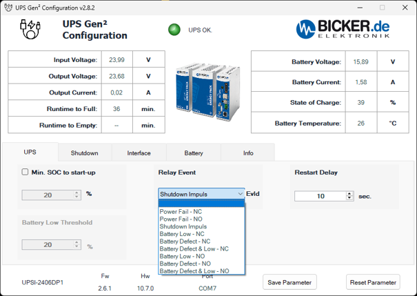
The power and battery overview at the top and the identification bar at the bottom appear in all five screenshots. These are read-only data; settings are changed in the individual tabs.
Common information on all screens
- Input Voltage [V]
- UPS input voltage. This value is available during normal operation from the upstream power supply.
- Output Voltage [V]
- Voltage at the UPS output supplying the connected equipment. It is displayed during both normal and battery operation.
- Output Current [A]
- Current drawn by the equipment connected to the UPS output.
- Runtime to Full [min.]
- Estimated charging time until the battery reaches 100% charge.
- Runtime to Empty [min.]
- Estimated remaining backup time under the current load. This is not a guaranteed operating time.
- Battery Voltage [V]
- Current battery voltage.
- Battery Current [A]
- Battery current. A positive value indicates charging; a negative value indicates discharging.
- State of Charge [%]
- Current battery state of charge, abbreviated SOC. The percentage thresholds for startup and shutdown use this value.
- Battery Temperature [°C]
- Temperature reported by the battery temperature sensor. Availability of this measurement depends on the battery module used.
- Status indicator and UPS OK.
- Indication of the current UPS operating state. The example shows a green indicator and the message UPS OK.
- Program name and version
- The title bar shows the configuration program name and version. The screenshots show UPS Gen² Configuration v2.8.2.
- UPS / Shutdown / Interface / Battery / Info
- Tabs for UPS settings, shutdown conditions, communication interfaces, battery data and device identification. The operating data overview at the top remains the same on all five screens.
- Device identification
- The connected UPS model is shown at the bottom left, here UPSI-2406DP1.
- Fw
- Version of the firmware installed in the UPS. The screenshots show 2.6.1. This is different from the version of the program on the computer.
- Hw
- UPS hardware version. The screenshots show 10.7.0.
- Port
- Communication port used by the program, here COM7. A USB connection can appear as a virtual serial port on the computer; the COM designation therefore does not mean that the UPS is being configured using an RS232 cable.
- Save Parameter
- Saves the modified parameters to the UPS. The configuration program can be closed after saving. The button is visible in the first screenshot.
- Reset Parameter
- Restores the default parameter values. This is not the button for saving settings normally.
UPS tab settings
- Min. SOC to start-up [%]
- Minimum battery charge required to enable the UPS output. After being switched on or restarted, the UPS waits until the battery reaches the set charge level before allowing power to the load. The range is 1 to 99 % in steps of 1 %. The screenshot shows 20 %, but the option is not checked.
- Battery Low Threshold [%]
- Low battery charge threshold for relay signalling. The range is 1 to 99 % in steps of 1 %. The screenshot shows 20 % and the field is inactive. This threshold is used for battery signalling; it is separate from the command to shut down the operating system.
- Restart Delay [sec.]
- Time for which the output remains off during a restart sequence before being switched on again. It provides a defined off period during which capacitances in the connected equipment can discharge. The range is 1 to 65 535 seconds; the screenshot shows 10 seconds. Automatic computer startup also requires the appropriate BIOS settings.
- Relay Event / EvId
- Selects the event signalled by the UPS relay contact. EvId means the identifier of the selected event. The screenshot shows the expanded list with Shutdown Impuls selected.
Relay Event menu options
- Power Fail - NC
- Signals a failure of the input power supply. With this option, the contact is closed during battery operation.
- Power Fail - NO
- Signals a failure of the input power supply with the opposite contact state. The contact is open during battery operation.
- Shutdown Impuls
- A short relay pulse to initiate computer shutdown. The relay is connected in parallel with the computer's power button. The pulse is associated with enabled shutdown by time or SOC.
- Battery Low - NC / Battery Low - NO
- Relay signalling of low charge according to Battery Low Threshold. NC and NO designate different contact logic. The actual contact state when the threshold is reached must be confirmed for the firmware used.
- Battery Defect - NC / Battery Defect - NO
- Relay signalling of a battery fault or an unrecognised battery. A confirmed trigger is a missing or unrecognised battery, which the UPS also indicates with LED status code 5. The NC and NO variants differ in their contact logic.
- Battery Defect & Low - NC / Battery Defect & Low - NO
- Names of options for combined signalling of a battery fault and low charge. The exact combination of trigger conditions and the contact state must be confirmed for the firmware used.
Relay settings depend on the supported UPS hardware and firmware version. Before connecting the relay to a machine control system, we will help verify the required event and the resulting contact logic.
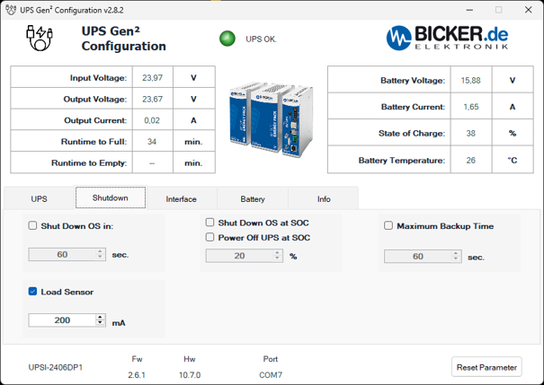
The upper section again displays power supply data, load current, battery charge and temperature; the bottom bar identifies the UPS, firmware, hardware and communication port. The Shutdown tab determines when computer shutdown begins or the UPS output is disconnected.
- Shut Down OS in [sec.]
- Time from the start of battery operation until the command to shut down the operating system is sent. The range is 1 to 65 535 seconds in steps of one second. If input power returns sooner, the timed shutdown condition does not take effect. The screenshot shows 60 seconds, but the option is not checked.
- Load Sensor [mA]
- Low load detection. If the load current falls below the set limit during battery operation, the UPS switches off its output and disconnects the energy storage device to limit discharge. The range is 50 to 4 000 mA in steps of 1 mA. In the screenshot, the function is enabled with a threshold of 200 mA.
- Shut Down OS at SOC [%]
- Initiates operating system shutdown when charge falls below the set threshold while the UPS is still running on battery power. The range is 1 to 99 % in steps of 1 %. The screenshot shows 20 %, but the option is not enabled.
- Power Off UPS at SOC
- Option for switching off the UPS according to its state of charge. It is separate from the Shut Down OS at SOC command. Its exact threshold and interaction with operating system shutdown must be confirmed for the firmware used; the option is not enabled in the screenshot.
- Maximum Backup Time [sec.]
- Maximum permitted time on battery power. Once it expires, the UPS disconnects its output, cutting power to the connected load. The range is 1 to 65 535 seconds. The screenshot shows 60 seconds, but the function is not enabled. When backing up a computer, allow sufficient time for a complete system shutdown; add a margin of at least 30% to the required shutdown time.
- Checkboxes
- Enable or disable the corresponding condition. A number shown in an unchecked field does not by itself mean that the function is active.
Using time and charge thresholds together: if both Shut Down OS in and Shut Down OS at SOC are enabled, whichever condition occurs first triggers shutdown.
Windows settings: for shutdown via USB HID, set the power button action to Shut down. Disable automatic sleep while on battery power; otherwise its low current draw could activate Load Sensor.
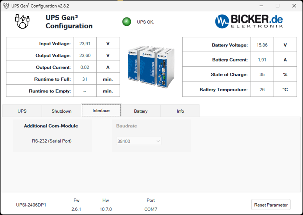
The upper operating overview and the bottom identification bar have the same meaning as in the first screenshot. This tab shows the UPS serial interface; the configuration program itself connects to the UPS via USB.
- Additional Com-Module
- Overview of the additional communication interface. The screenshot shows RS-232 (Serial Port).
- RS-232 (Serial Port)
- UPS serial interface for exchanging data with a connected system. Its presence on this tab does not change the USB connection used for configuration.
- Baudrate
- Serial line transmission rate. The screenshot shows 38 400 baud and the field is inactive. The RS232 protocol specifies 8 data bits, 1 stop bit, no parity and DTR enabled.
- Port COM7
- Port through which the configuration program communicates with the UPS. With USB CDC, this is a virtual serial port; the Baudrate value is not relevant to this USB data transfer.
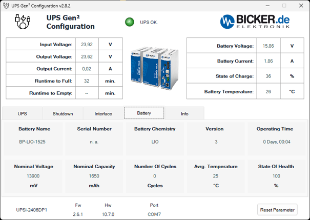
This tab displays identification and operating data reported by the battery module. It is not a form for changing the battery type or capacity. The upper overview continues to show its instantaneous voltage, current, charge and temperature.
- Battery Name
- Designation of the connected energy storage device, here BP-LIO-1525. It identifies the battery module.
- Serial Number
- Serial number reported by the battery. The example shows n. a., meaning the data is not available. This is different from the UPS serial number on the Info tab.
- Battery Chemistry
- Battery chemistry. The abbreviation LIO in the example denotes Li-Ion.
- Version
- Version reported by the battery module, here 3. This is neither the configuration program version nor the firmware version of the entire UPS.
- Operating Time
- Displayed operating time counter in days, hours and minutes; the example shows 0 Days, 00:04. This value alone does not establish the battery's manufacturing date or age.
- Nominal Voltage [mV]
- Nominal voltage reported by the battery module in millivolts. It is separate from the instantaneous Battery Voltage shown in the upper overview.
- Nominal Capacity [mAh]
- Nominal capacity reported by the battery module in milliampere-hours. This is neither the current charge percentage nor a backup time value.
- Number of Cycles [Cycles]
- Number of full charge and discharge cycles reported by the battery. Availability of the counter depends on battery module support.
- Avg. Temperature [°C]
- Average temperature reported in the battery overview. It is different from the instantaneous Battery Temperature at the top of the window.
- State of Health [%]
- Battery health indicator, abbreviated SOH. Do not confuse it with SOC, the current state of charge. SOH support must be confirmed for the specific battery module and firmware; a displayed value of 100 % alone does not confirm a measured remaining battery capacity.
The values in the screenshot relate to one specific connected setup. When designing a backup system, use the specifications of the supplied model and battery rather than the figures in this program example.
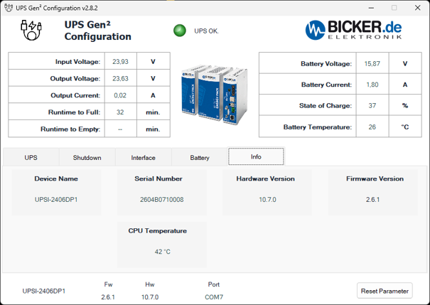
This tab summarises the information needed for device identification, version checks and technical support. The upper section displays the same power supply and battery operating data as the previous screens.
- Device Name
- Model of the connected UPS. The screenshot shows UPSI-2406DP1.
- Serial Number
- Serial number of the UPS itself, used to identify the individual unit for technical support or servicing.
- Hardware Version
- UPS hardware version, here 10.7.0. The same value appears as Hw in the bottom bar.
- Firmware Version
- UPS internal firmware version, here 2.6.1. The same value appears as Fw in the bottom bar. In program version 2.4.2 and later, clicking the firmware version text on the Info tab opens the firmware update function.
- CPU Temperature [°C]
- Temperature of the processor in the UPS control electronics. This is neither the battery temperature nor the temperature of the connected computer.
- Bottom bar and Reset Parameter
- The model, Fw, Hw and Port repeat the identification and connection information. Reset Parameter restores the default UPS parameters; its meaning remains the same when switching tabs.
Schedule an online meeting
Do you need advice on backup time, wiring, or connecting the power supply to your equipment? Choose a time for a short online consultation directly in the calendar below.
Technical parameters
Basic features
- Device type: intelligent DC UPS module for 24 V systems
- Model: UPSI-2406DP1
- Input voltage: 24 VDC (range 22.5–30 VDC)
- Output voltage: normal mode VIN − 0.5 VDC max. (depending on load) / backup mode regulated 23.5 VDC
- Output current: 4 A nominal
- Power: 96 W
- Energy storage technology: Li-Ion battery
- Mounting: on DIN rail according to EN 60715
Backup power and Li-Ion battery
- Battery type: Li-Ion
- Battery capacity: 2.5 Ah / 37 Wh
- Backup time: approx. 12 min at an output current of 4 A
- Charging time: approx. 55 min at maximum charging current
- Battery lifetime: up to 500 charge and discharge cycles
- Nominal battery voltage: 14.8 V
- Final charging voltage: 15.9 V
- Max. battery charging current: 1 C
- Battery undervoltage protection: 10.8 V
- Charging method: CC / CV / CP
Output and power
- Dynamic output current: 4–6 A temporarily
- Short-term SFB current: 30 A for 5 ms
- Dynamic power: 96–144 W temporarily
- Power in backup mode: 94 W nominal
- Dynamic power in backup mode: 94–141 W temporarily
- Switching time: <600 µs
- Capacitive load: max. 3000 µF (at startup, 0 A load)
- Overcurrent protective shutdown: 4–6 A max. 58 s depending on dynamic load; 6–10.8 A max. 100 ms; above 10.8 A max. 5 ms
Input parameters and power supply
- Max. input dielectric strength: 35 VDC
- Fixed undervoltage connection threshold: 22.5 VDC
- Input/output voltage drop: max. 0.5 VDC (depending on load)
- Input current: 4.1 A nominal
- Max. input current: 4.8 A
- Dynamic input current: 4.1–6.1 A temporarily
- No-load input current: <100 mA
- Charging current from input: 1.8 A
- Power consumption: 98.5 W nominal / 115 W max.
- Dynamic power consumption: 98.5–146.5 W temporarily
- Power consumption during charging: 43 W
- Input fuse: yes, 15 A
- Startup time: <5 s
- Battery-only start: not supported
- Recommended power supply: min. 24 V / 5 A (120 W); when using Dynamic Powerboost min. 24 V / 6.25 A (150 W)
Communication and signalling
- Communication interfaces: USB, RS232, HID UPS
- USB interface: USB 2.0, USB-B connector, VCOM / HID protocols, max. cable length 3 m
- RS232 interface: 9-pin DSUB, 38400 baud, TX/RX, 1:1 cable, max. length 10 m
- Signalling: potential-free relay contact for Power Fail Alarm
- Relay contact: max. 24 VDC / 1 A or 125 VAC / 0.5 A, NO / NC configurable by software
- Configuration: via UPScom software / UPS Gen2 Configuration Software
Functions and protection
- Functions: intelligent Power Sharing, regulated output voltage in backup mode, minimum-load detection, power-failure timer, controlled system shutdown, automatic restart of the connected device, state-of-charge indicator, external shutdown signal, Plug & Play recognition as a UPS by the operating system
- Dynamic Powerboost: temporary increase of output power up to 144 W, for a maximum of 58 s depending on the energy drawn
- Protection: input reverse-polarity protection when the device is switched off, overcurrent protection, output short-circuit protection, no-load operation protection, and battery deep-discharge protection
- Parallel UPS connection: not supported
- Series UPS connection: not supported
Standards and certifications
- Safety standards: IEC 61010-1 / IEC 61010-2-201 (SELV)
- Certifications: ETL UL 61010-1 / UL 61010-2-201, CSA C22.2 61010-1-12 / CSA C22.2 61010-2-201, CB Scheme IEC 61010-1 / IEC 61010-2-201
- Electrostatic discharge immunity: 4 kV contact discharge / 8 kV air discharge according to EN 61000-4-2
- Electrical fast transient immunity: 2 kV according to EN 61000-4-4
- Surge immunity: ±0.5 kV L–N / ±1 kV L–PE and N–PE according to EN 61000-4-5
Operating conditions
- Operating temperature: 0 to +50 °C
- Storage and transport temperature: −20 to +50 °C
- Max. humidity: ≤95 % at +25 °C, non-condensing
- Max. altitude: ≤4000 m
- Climatic class: 3k3 according to EN 60721
- Pollution degree: 2
- Overvoltage category: I according to EN 61010-1 / EN 61010-2-201
- Use: indoor environment / outdoor environment only in a suitable enclosure
Mechanical design
- Protection rating: IP20
- Protection class: III
- Enclosure material: aluminium
- Flammability class: V0 according to UL 94
- Dimensions (W × H × D): 63 × 120 × 100 mm (without front connectors and DIN rail mounting bracket)
- Weight: 0.6 kg
Frequently asked questions about the Bicker UPSI-2406DP1 backup power supply
Basic use and backup power
What is the Bicker UPSI-2406DP1?
The UPSI-2406DP1 is an intelligent industrial DC/DC UPS backup power supply for equipment powered by 24 VDC. It offers a nominal output current of 4 A, power of 96 W, and an integrated Li-Ion battery with a capacity of 2.5 Ah / 37 Wh. It is designed for DIN rail mounting in a control cabinet.
How does a DC UPS work in an industrial application?
The UPS is connected between an external 24 VDC power supply and the protected device. In normal mode, it passes the input voltage to the output while charging the integrated Li-Ion battery. The charging current dynamically adapts to the current consumption of the connected load.
When the input voltage fails or drops below a specified threshold, the UPS automatically switches to backup mode. It then powers the connected device from the battery and regulates the output voltage to 23.5 VDC.
How does the UPSI-2406DP1 differ from the UPSI-2406DP2 and UPSI-2406DP3?
All three models are intelligent DC UPS units for 24 VDC systems, mount on a DIN rail, and support USB, RS232, HID UPS, controlled shutdown, Reboot, Load Sensor, and other configurable functions. The main differences are the energy storage technology, available power, and backup time.
- UPSI-2406DP1: 24 VDC / 4 A / 96 W, integrated Li-Ion battery, 2.5 Ah / 37 Wh. At a current draw of 4 A, it provides approximately 12 minutes of backup time. It is suitable where several minutes of operation during a power failure are required.
- UPSI-2406DP2: 24 VDC / 4 A / 96 W, integrated supercapacitors, 5.73 kJ / 1.59 Wh. At 4 A, it provides approximately 30–35 seconds of backup time, but supports up to 500,000 charge and discharge cycles. It is particularly suitable for frequent short power failures.
- UPSI-2406DP3: 24 VDC / 6 A / 144 W, integrated LiFePO₄ battery, 2.5 Ah / 33 Wh. It offers a higher nominal current and power than DP1 and DP2 and, at 6 A, provides approximately 11 minutes of backup time.
The UPSI-2406DP1 is therefore particularly suitable for 24 VDC devices with current consumption of up to 4 A where several minutes of backup power are required. The UPSI-2406DP2 is more suitable for very frequent short power failures, while the UPSI-2406DP3 is intended for equipment with higher consumption of up to 6 A.
Is a separate 24 V power supply required upstream of the UPS?
Yes. The UPSI-2406DP1 is a DC/DC UPS, not an AC/DC mains power supply. It requires an external 24 VDC power supply.
For full functionality at nominal load, the manufacturer recommends an upstream power supply rated at least 24 V / 5 A / 120 W. If you want to use the Dynamic Powerboost function, use a power supply rated at least 24 V / 6.25 A / 150 W.
What are the UPS input and output voltages?
The nominal input voltage is 24 VDC and the permitted input range is 22.5–30 VDC. In normal mode, the output follows the input voltage with a drop of up to 0.5 V depending on the load.
In backup mode, the UPS provides regulated 23.5 VDC regardless of the gradual battery-voltage decrease during discharge.
How quickly does the UPS switch during a power failure?
The switch from normal to backup mode takes less than 600 µs, or less than 0.6 ms. The connected 24 VDC device can therefore continue operating without a typical restart caused by a power failure.
Does the UPS have a Battery Start function?
No. The UPSI-2406DP1 does not support startup solely from the integrated battery without input power. It is put into operation by connecting a suitable external 24 VDC power supply.
Battery and backup time
What are the battery capacity and type?
The UPSI-2406DP1 contains an integrated Li-Ion battery with a nominal voltage of 14.8 V and a capacity of 2.5 Ah / 37 Wh. The manufacturer specifies a lifetime of up to 500 charge and discharge cycles.
How long can the UPS power a device?
Backup time depends on the consumption of the connected device, temperature, current charge level, and battery condition. At the nominal output current of 4 A, the manufacturer specifies an approximate backup time of 12 minutes at +25 °C.
Backup time increases at lower current draw. It may decrease at very high or low temperatures.
How long does battery charging take?
The manufacturer specifies an approximate charging time of 55 minutes at maximum charging current. The actual time depends on the battery discharge level, input voltage, and the current that the UPS simultaneously supplies to the connected device.
How does the UPS protect the Li-Ion battery against deep discharge?
The UPS continuously monitors the battery condition and has undervoltage protection set to 10.8 V. When this limit is reached, it ends backup operation to prevent excessive battery discharge.
Is a Li-Ion battery better than supercapacitors?
It depends on the required backup time and frequency of power failures. The Li-Ion battery in the UPSI-2406DP1 provides approximately 12 minutes of backup time at 4 A, making it suitable for bridging a longer power failure or safely shutting down a system.
The UPSI-2406DP2 with supercapacitors provides a much shorter backup time but supports a very high number of charge and discharge cycles. It is therefore particularly suitable for recurrent short power failures.
Installation and operating conditions
How is the UPSI-2406DP1 mounted?
The UPS is designed for DIN rail mounting according to EN 60715. The manufacturer recommends vertical mounting on a horizontal DIN rail to ensure proper cooling by natural convection.
How much space must be left around the UPS?
For adequate cooling, the manufacturer recommends leaving at least 20 mm of free space to the left and right of the UPS and at least 50 mm above and below the device. Ventilation openings must not be covered.
Is the UPSI-2406DP1 suitable for outdoor use?
The UPS itself has an IP20 protection rating and is therefore not intended for unprotected outdoor installation. The manufacturer permits use indoors and outdoors only if the UPS is installed in a suitable enclosure that provides protection against water, fire, and electrical hazards.
What is the UPSI-2406DP1 operating temperature?
The operating temperature of the UPSI-2406DP1 is 0 to +50 °C. The storage and transport temperature is −20 to +50 °C. Available battery capacity and backup time can change at very high or low temperatures.
What are the UPS dimensions and weight?
The UPS dimensions are 63 × 120 × 100 mm without front connectors and the DIN rail mounting bracket. The weight is approximately 0.6 kg.
Can multiple UPS units be connected in series or parallel?
No. The UPSI-2406DP1 is not intended for series or parallel connection of multiple UPS modules. Each backup power supply must be designed separately for a specific 24 VDC load.
Power, protection, and communication
What power can the UPS supply?
The nominal output current is 4 A, which corresponds to a power of 96 W during normal operation. In backup mode, the manufacturer specifies a nominal power of approximately 94 W at a regulated output voltage of 23.5 VDC.
What is Dynamic Powerboost?
Dynamic Powerboost enables the UPS to temporarily provide a current higher than the nominal 4 A. The output current can increase to 4–6 A, or up to approximately 144 W in normal mode.
The duration is not fixed at 58 seconds for every load. The UPS evaluates the energy drawn, and the maximum Dynamic Powerboost time is 58 seconds. Therefore, always design equipment for a continuous nominal current of 4 A.
Can the UPS handle a short inrush-current peak when equipment starts?
Yes. The UPS supports a short-term SFB current of up to 30 A for 5 ms. This value is intended for very short current peaks and cannot be considered a continuously available output current.
How does the UPS protect itself and the connected load?
The UPS has input reverse-polarity protection when connecting a switched-off device and output protection against overcurrent and short circuit. The output is also resistant to no-load operation.
When the permitted current is significantly exceeded, the UPS disconnects the output quickly. However, input reverse-polarity protection does not apply when connecting a reversed-polarity input during active backup operation, so correct polarity must always be verified before connection.
How can the UPS status be monitored?
Basic operating states are indicated by a status LED. The UPS can be connected to a computer via USB. Supported operating systems can recognize it using Plug & Play as a HID UPS or HID Battery class device without installing a separate driver.
UPS Gen2 Configuration Software is available for parameter settings and firmware updates. UPScom can be used for continuous monitoring, controlled shutdown, email notifications, or running custom scripts.
What communication interfaces does the UPS support?
The UPSI-2406DP1 supports USB 2.0 with a USB-B connector, the RS232 serial interface, and HID UPS. RS232 uses a 9-pin D-Sub connector and a transmission rate of 38400 baud.
A potential-free relay contact for power-failure signalling is also available.
What can the relay contact switch?
The potential-free relay contact is primarily intended for signalling an operating status, such as a power failure. The contact is rated for a maximum of 24 VDC / 1 A or 125 VAC / 0.5 A. The NO or NC function can be configured by software.
How does the Load Sensor work?
The Load Sensor monitors the current drawn by the connected device. If consumption falls below a configured value after controlled shutdown of a computer or another system, the UPS can evaluate this condition as completed shutdown and subsequently end backup power supply.
This prevents unnecessary battery discharge after the connected device has been switched off.
Can the UPS safely shut down an industrial computer?
Yes. Via USB and UPScom software, the UPS can initiate a controlled computer shutdown during a power failure. For example, shutdown delay, maximum backup time, minimum battery state before system startup, or execution of a custom program or script before shutdown can be configured.
It is necessary to verify that the specific computer can complete all required operations within the available backup time.
What does the Reboot function do?
The Reboot function helps automatically restore operation of the connected system after input power returns. For an industrial computer, the BIOS and operating system must also be configured correctly so that it can start automatically after power is restored.
What applications is the UPSI-2406DP1 suitable for?
The UPS is suitable, for example, for industrial computers, machine controllers, communication equipment, network devices, measuring devices, and other electronics powered by 24 VDC that must continue operating or shut down safely during a power failure.
The manufacturer specifies it for professional use, for example in industrial control, communication, and measurement technology. It is not intended for applications where its failure could directly cause serious injury or endanger human life.
Highlighted items are mandatory.