

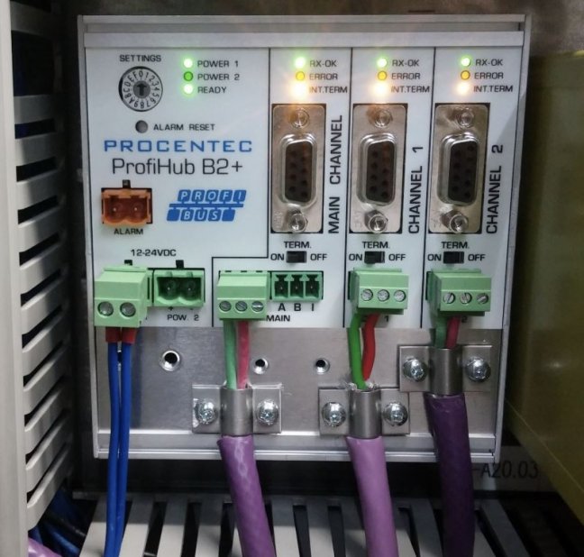
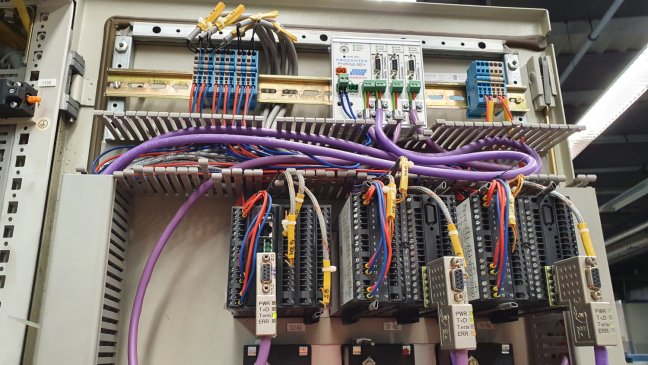


ProfiHub B2+R multi-repeater PROFIBUS

The ProfiHub B2+R enables you to create up to 2 new star segments, with each of them allowing for further stations to be connected and a longer PROFIBUS cable. In addition, the ProfiHub B2+R amplifies the signal and filters out glitches between segments, which helps to improve the robustness of the network. When you turn on the diagnostic mode, the ProfiHub starts to act as Slave and provide the Master with data about communication and network faults. More
Code: 17210R
The ProfiHub B2+R enables you to create up to 2 new star segments, with each of them allowing for further stations to be connected and a longer PROFIBUS cable. In addition, the ProfiHub B2+R amplifies the signal and filters out glitches between segments, which helps to improve the robustness of the network. When you turn on the diagnostic mode, the ProfiHub starts to act as Slave and provide the Master with data about communication and network faults. More
Code: 17210R
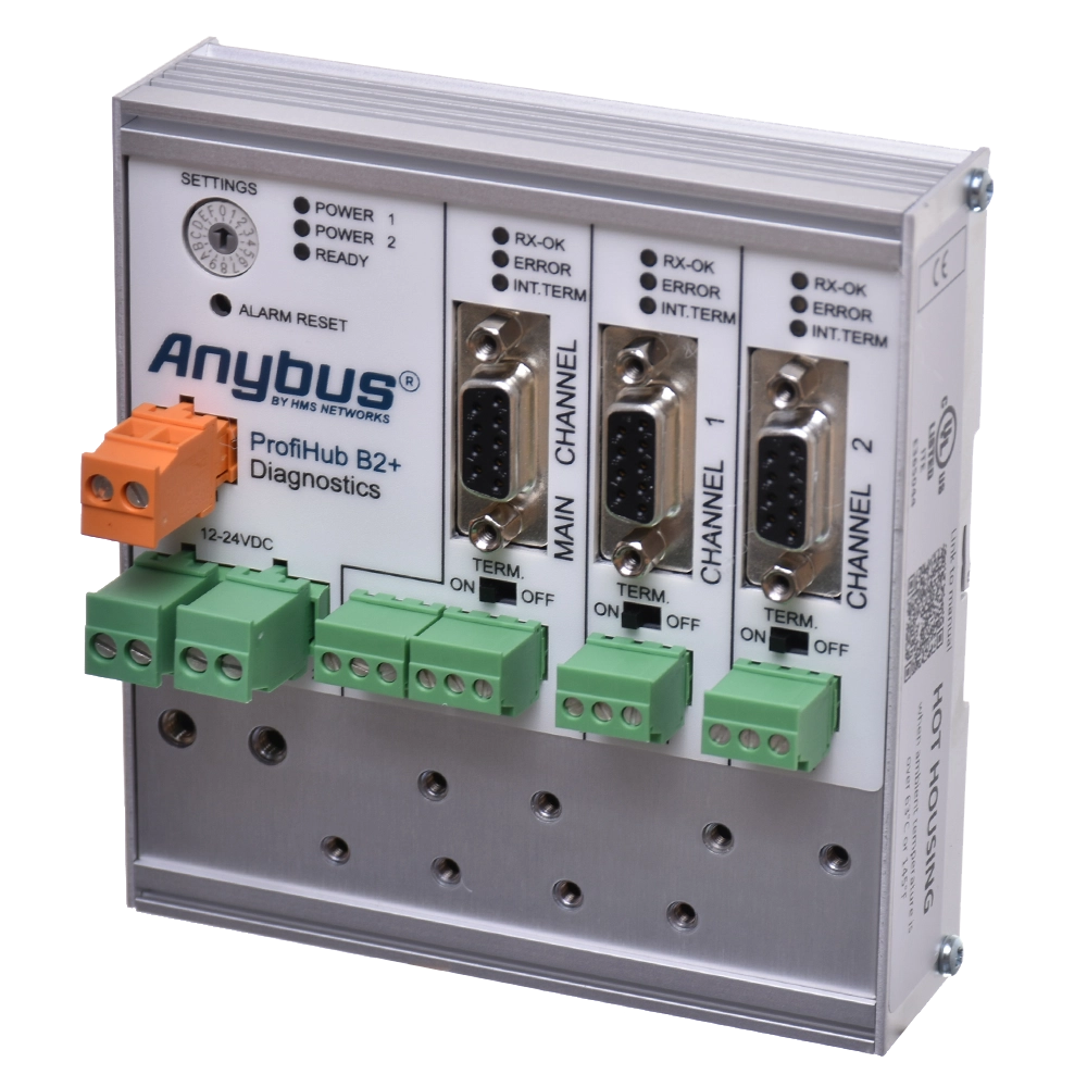
PROFIBUS DP · MAIN + CH1 + CH2
ProfiHub B2+R
Three galvanically isolated segments
Network redundancy and diagnostics
You can create two separate active segments from a single PROFIBUS DP segment. The ProfiHub B2+R regenerates the signal, separates the segments and provides two cable paths for a redundant connection. The built-in diagnostic slave transmits status information and statistics to the PLC, DCS and the ComBricks permanent PROFIBUS network analyser.
Please send us the topology, network speed and number of stations. We will check the connections and required accessories.
Better signal quality and longer PROFIBUS network operation
The ProfiHub B2+R is one of our best-selling products for PROFIBUS networks. It improves signal quality, helps minimise downtime caused by poor signal quality and extends the operational life of your existing network.
Integration into the network is straightforward and, in normal repeater mode, does not require any modification to the PLC program. When splitting the original long cable, cut the PROFIBUS cable at the selected points and connect the resulting sections to a powered ProfiHub. This creates shorter segments that are galvanically isolated from one another. Each of these must be correctly terminated at both ends with a resistor that is switched on and powered.
In normal repeater mode, the order in which the individual segments are connected to the MAIN, CH1 and CH2 channels does not matter. However, always ensure the correct polarity of the A/B wires and the terminations. When redundancy is used, CH1 and CH2 are designated as the redundant pair.
ProfiHub regenerates the signal transmitted to the individual segments. Galvanic isolation limits the propagation of electrical faults and electromagnetic interference between segments. Proper shielding and bonding remain important for protection against electrostatic interference as well. When installed correctly, ProfiHub thus helps to keep the PROFIBUS network running reliably for years to come.
Normal repeater operation does not require changes to the PLC program. Enabling the diagnostic slave requires adding the GSD file and configuring the device; using its data in the PLC or HMI also requires data processing. Robust Repeating and redundancy modes require the bus timing to be checked.
Two new active segments from one main segment
A segment is a section of the network in which the electrical signal is the same. Each segment must be properly terminated at both ends with a termination resistor that is switched on and powered.
ProfiHub supports star and tree topologies. The new RS485 segments feature their own terminations, galvanic isolation and short-circuit protection.
Extension of the line
Connect another group of peripherals, drives or instruments to a separate active segment.
Maintenance in stages
Group the stations by machine or control cabinet. This gives you a smaller section of the network to investigate when troubleshooting.
A measurement point on each segment
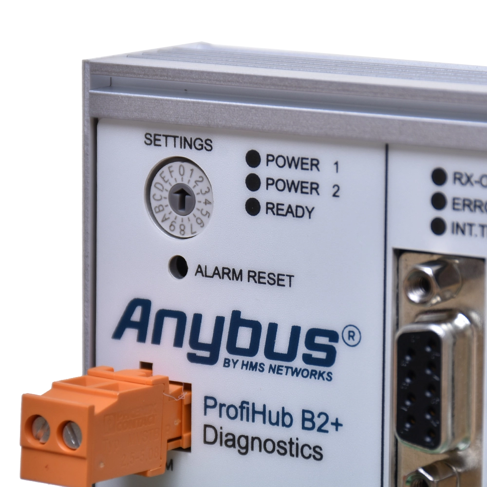
DB9 connectors are used to connect the bus and the ProfiTrace 2 analyser when checking the signal.


Limiting electrical faults between segments
Galvanic isolation and short-circuit protection help to isolate an electrical fault in one segment from the others. ProfiHub restores the signal and suppresses short, disruptive pulses.
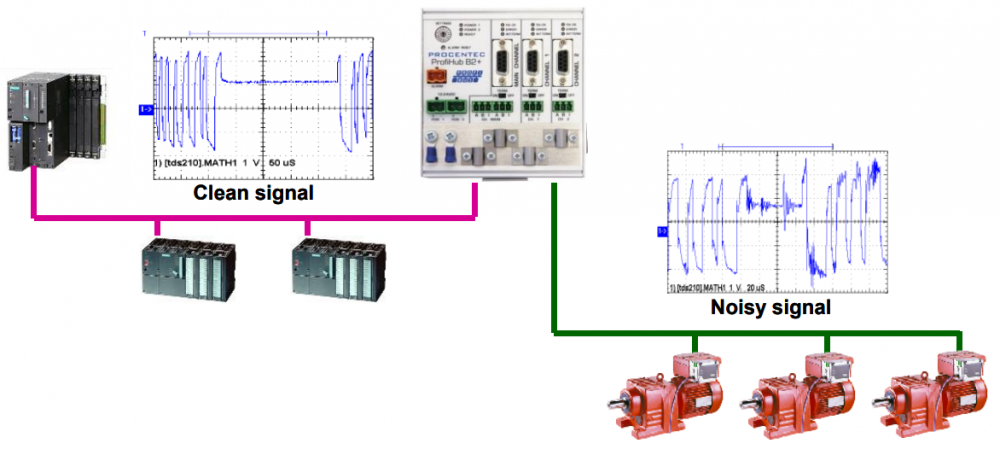
The disconnection of a station or a fault in a segment will still affect the equipment on that segment and the response of the control program. Network segmentation is therefore no substitute for proper shielding, bonding and termination.
Robust Repeating is an optional mode. It checks the start of the telegram before transmitting the data. This does not involve correcting arbitrarily corrupted messages. This mode increases the delay, so it is necessary to check the bus timing and adjust the MinTSDR setting on the master.
Cable length depending on network speed
Each channel can connect up to 31 additional devices, including further hubs, optical converters and measuring instruments. The maximum length applies to a correctly installed PROFIBUS DP RS485 cable.
| Speed | Maximum segment length |
|---|---|
| 9.6 / 19.2 / 45.45 / 93.75 kbit/s | 1 200 m |
| 187.5 kbit/s | 1 000 m |
| 500 kbit/s | 400 m |
| 1.5 Mbit/s | 200 m |
| 3 / 6 / 12 Mbit/s | 100 m |
FOXON’s recommendation: Where the topology allows, divide the network into smaller groups, for example of 5 to 10 stations. This is a practical recommendation for easier maintenance, not a technical limit of the device.
The number of ProfiHubs that can be cascaded is limited by network timing and cumulative delay. Check the number of repeaters against the selected speed, operating mode and master parameters.
Terminal blocks, DB9s and switchable terminators
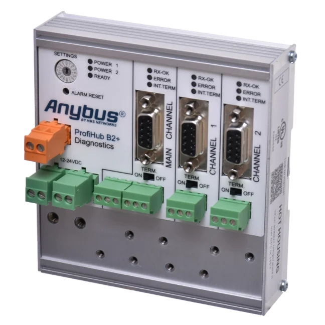
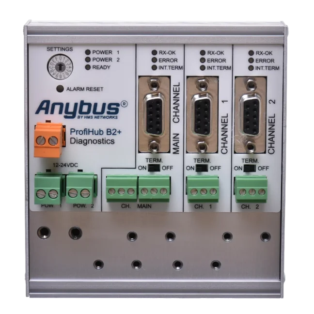
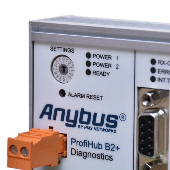
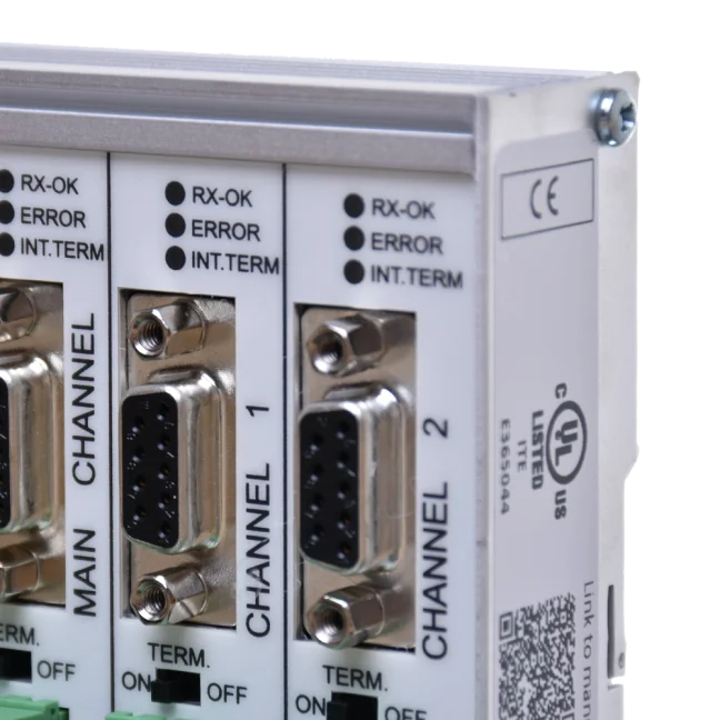
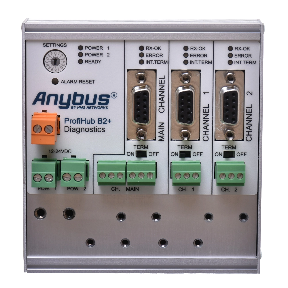
Connect the main segment to MAIN, and new segments to CH1 and CH2. Removable terminal blocks and DB9 connectors are available. Terminal A is for the green wire and terminal B is for the red wire of the PROFIBUS cable.

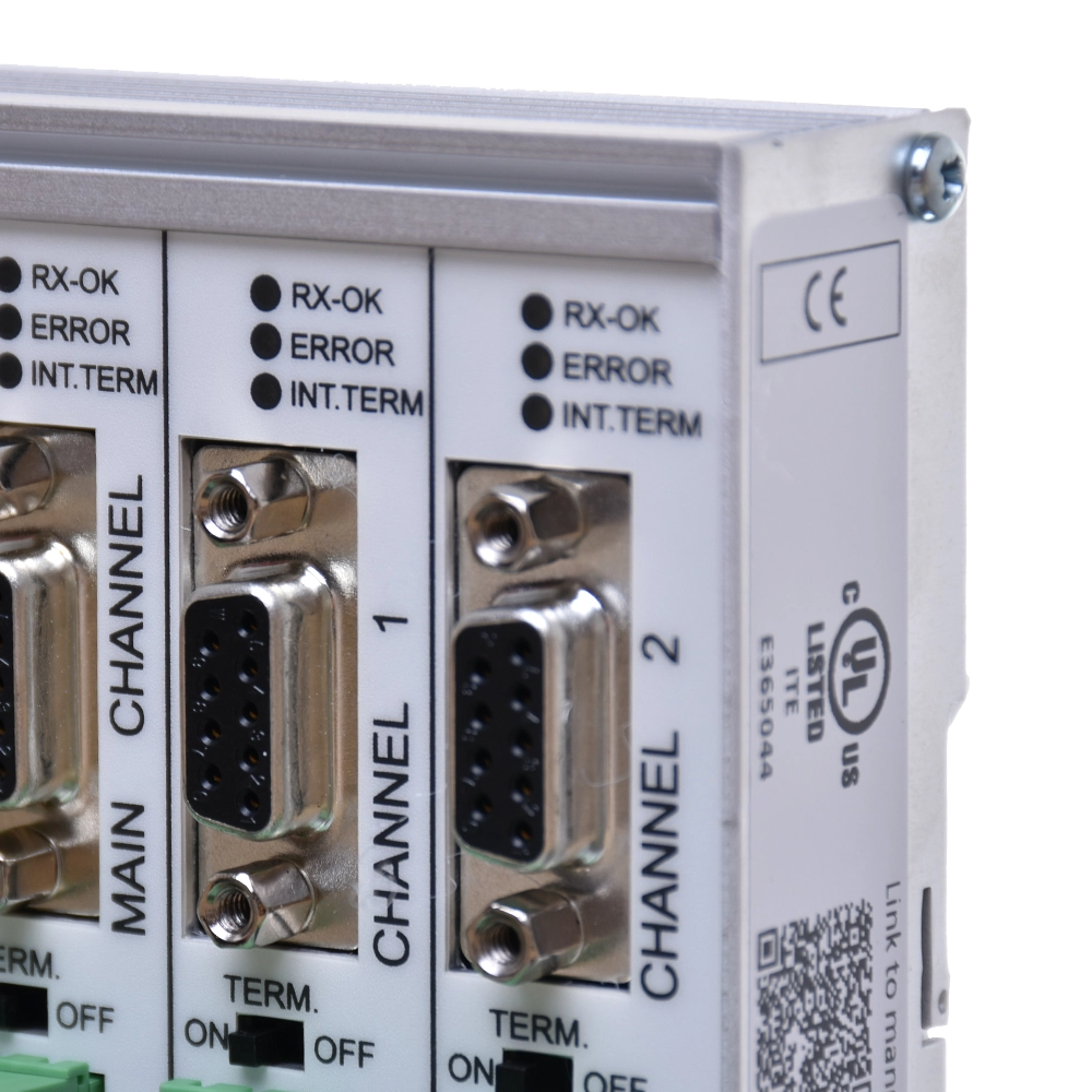
Active terminations must be fitted at both ends of each segment. The default setting for MAIN is OFF, whilst for CH1 and CH2 it is ON. Always adjust the settings to match the actual position of the ProfiHub in the network, and do not combine two terminations at a single point.
When connecting a segment via a DB9, select either a connector termination or a ProfiHub termination, depending on the wiring configuration. If the segment is to remain terminated even after the connector has been disconnected from the hub, use the termination within the connector. The shield can be connected directly or capacitively via terminal I.
PROFIBUS cable redundancy via CH1 and CH2 channels
Channels CH1 and CH2 form a redundant pair between two compatible devices. Telegrams are transmitted over both cable paths; if one cable is interrupted, the other path remains available.

In this mode, both outgoing channels are used for a single redundant connection. Check that this is supported and that the settings are correct at both ends. A fault in the path is indicated by the ERROR LED and the alarm contact; once the fault has been rectified, the alarm is acknowledged by pressing the ALARM RESET button.
The diagram illustrates the principle of redundancy in the ProfiHub family. For the B2+R, use the channels CH1 and CH2. Redundant mode uses Robust Repeating, so please check the master’s timing; particular attention should be paid to the connection with ComBricks.
Status and statistics sent directly to the PLC
Once activated, the built-in diagnostics function acts as a PROFIBUS DP-V0 slave. Add the GSD PROC6971.gsd to the master project, set the address and select the required data modules.
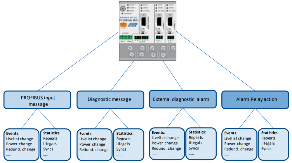
- Equipment statusesPower supply, relays, redundant connections and data transfer rate.
- Overview of segmentsTermination status, communication status and a list of available stations on each channel.
- Communication statisticsLoss of stations, SYNC, repeated queries, corrupted messages, and internal or external diagnostics.
- Event reportingInput data for PLCs/DCSs, diagnostic messages and configurable alarm relay activation.
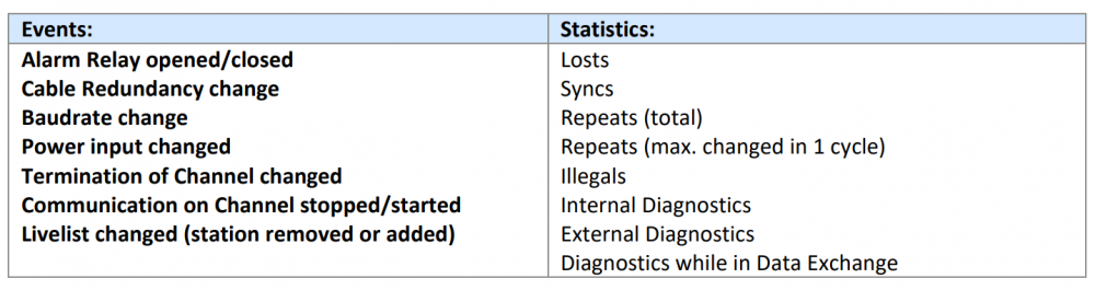
The default address of the diagnostic slave is 126. You can change this using the tool with the Set Slave Address command. The maximum data range is 85 bytes for inputs and 5 bytes for outputs.
ComBricks displays the supported data in its web interface; the data can also be analysed using ProfiTrace or a custom PLC/HMI application. The ProfiHub B2+R itself does not have an Ethernet web interface.

Modes by serial number
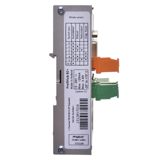
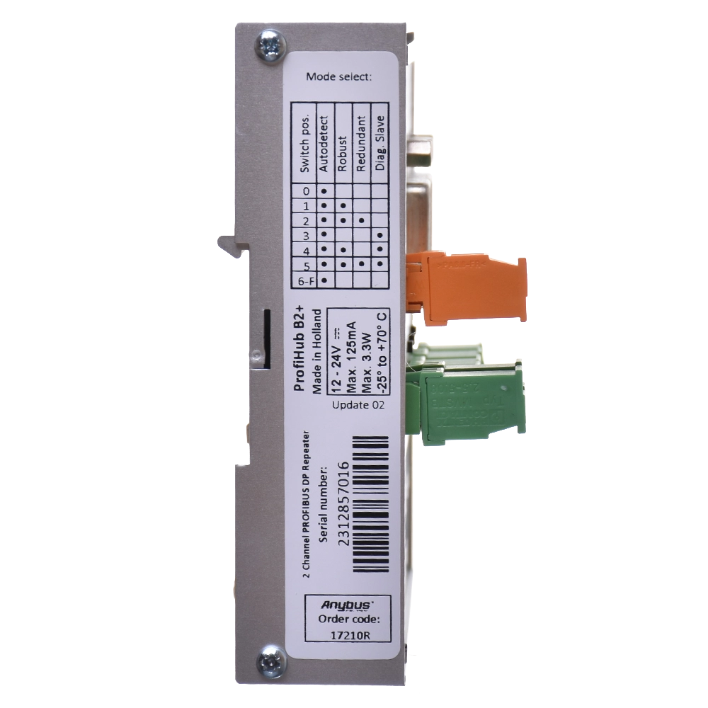
For units with a serial number starting with 19 or higher, the following overview applies. In all the positions listed, the speed is detected automatically.
| Switch position | Repeating mode | Redundancy | Diagnostic slave |
|---|---|---|---|
| 0 | Normal repeating | No | No |
| 1 | Robust Repeating | No | No |
| 2 | Robust Repeating | CH1 + CH2 | No |
| 3 | Normal repeating | No | Yes |
| 4 | Robust Repeating | No | Yes |
| 5 | Robust Repeating | CH1 + CH2 | Yes |
The switch position is read upon power-up. Once changed, the device must be powered off and on again. Older units with a serial number starting with 18 or lower have a different assignment of positions, including a fixed-speed option. Please check the label on your specific device before making any settings.
Two power inputs and a potential-free contact
ProfiHub operates on a 12–24 V DC power supply and offers two inputs for redundant power supply. If one power supply fails, the other takes over. For operation without redundancy, a single input is sufficient.
The current draw at 24 V and full load on all channels is 125 mA; the maximum power dissipation is 3.3 W. The power supply is protected against reverse polarity.
The alarm contact can be connected, for example, to a PLC digital input or to a signalling system. It is potential-free, with a limit of 24 V DC / 0.5 A. It can be used to indicate a power failure, a fault in the redundant path, or configured diagnostic events.
When using a single power supply input, the device will treat the absence of a second input as an alarm. If you connect the same power source to both inputs, you will clear this message, but you will not achieve the redundancy provided by two independent power sources.
ProfiHub B2+R, order number 17210R
| Order number | 17210R |
|---|---|
| Number of segments | 3: MAIN + CH1 + CH2; two galvanically isolated output channels |
| Interface | PROFIBUS DP RS485, detachable terminal blocks and DB9 |
| Transfer rate | 9.6 kbit/s to 12 Mbit/s, including 45.45 kbit/s |
| Transparent transmission | DP-V0 / DP-V1 / DP-V2, FDL, MPI, FMS, PROFIsafe and PROFIdrive |
| Devices per channel | Up to 31 additional devices; this includes hubs and connected analysers |
| Termination | Integrated, powered, switchable for each segment |
| Cable redundancy | Optional, via CH1 and CH2 |
| Diagnostic slave | DP-V0; GSD PROC6971.gsd; identification number 6971 |
| Diagnostic slave address | Default 126, change via software |
| Diagnostic data | Max. 85 bytes of input / 5 bytes of output |
| Power supply | 12–24 V DC; two redundant inputs, reverse polarity protection |
| Current consumption | 125 mA at 24 V DC, all channels fully loaded |
| Power dissipation | Max. 3.3 W |
| Alarm relay | Potential-free contact, max. 24 V DC / 0.5 A |
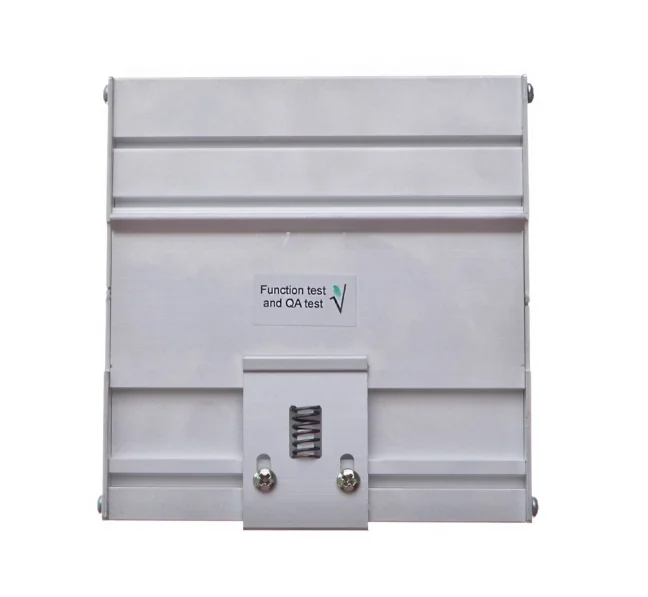
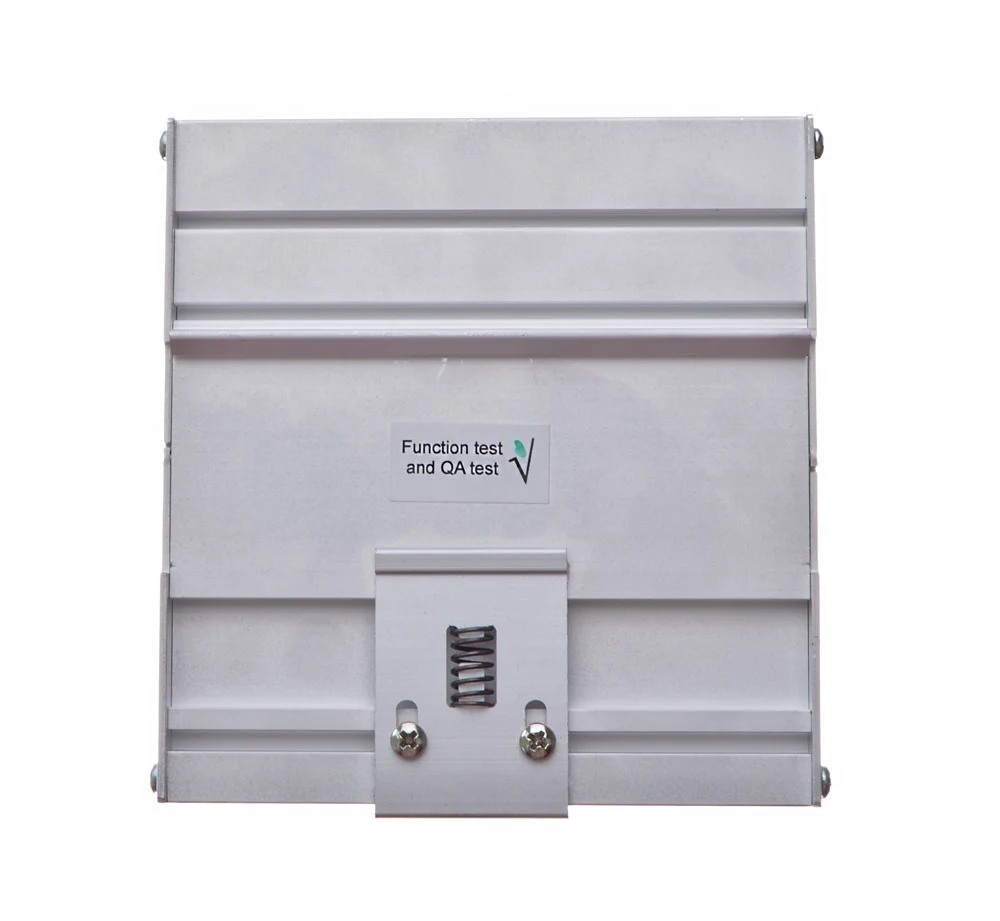
| Installation | DIN rail 35 × 7.5 mm; recommended orientation with cables facing downwards |
| Protection rating / temperature | IP20 / -25 to +70 °C |
| Dimensions and weight | We will confirm these values for the hardware revision of the supplied unit before planning the installation. |
PROFIsafe’s transparent transmission does not replace an application safety assessment. When installing, allow sufficient space for connectors and cable bends. Please check the dimensions, weight and mechanical design against the revision of the item ordered.
Star and tree networks
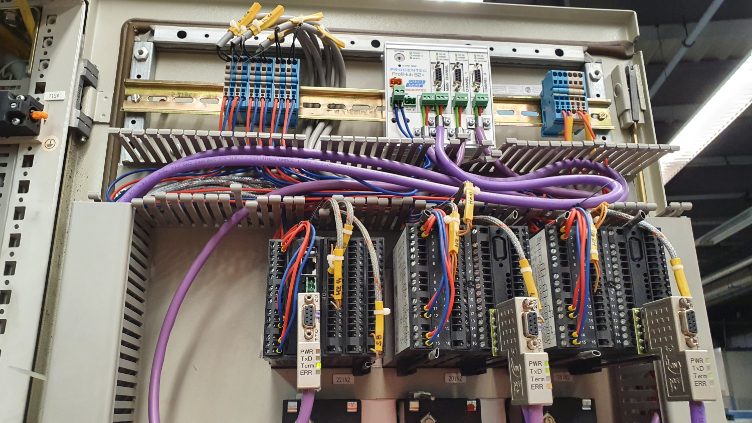
Divide the individual segments by machine, switchboard or cabling route. Combining several ProfiHubs will enable communication to be extended to other parts of the facility.
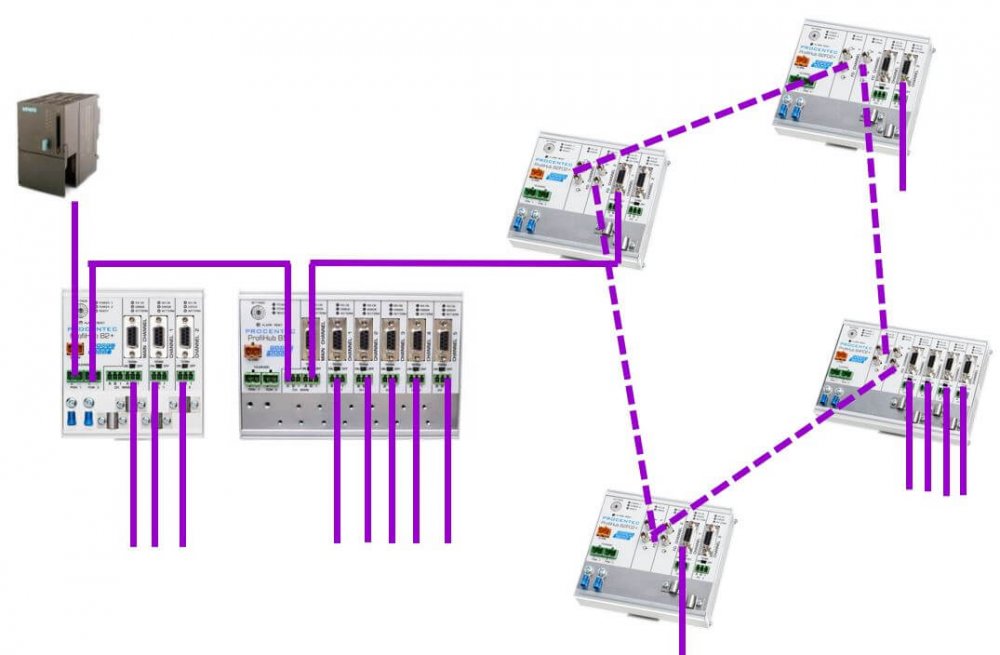
The example topology combines different members of the ProfiHub family. The B2+R is a copper repeater; fibre-optic connections require suitable fibre-optic equipment.
When taking the section to be disconnected out of service, ensure that the power supply and terminations for the other segments remain intact. The PLC’s response to the loss of peripherals is determined by its configuration and program.
Module and installation accessories
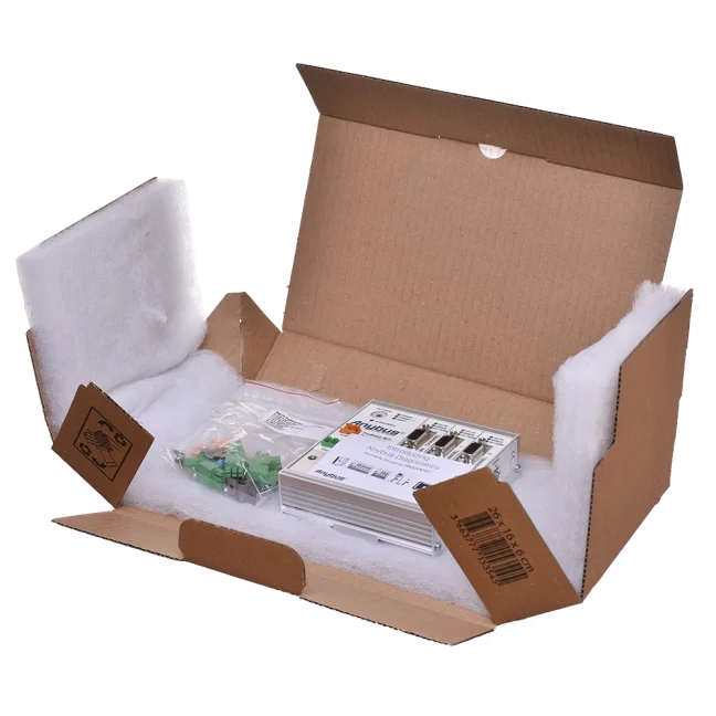
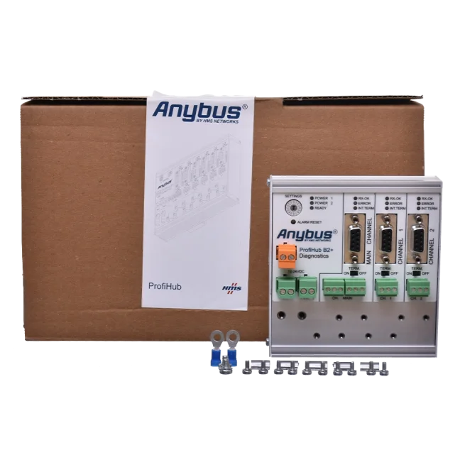
We will supply the ProfiHub B2+R 17210R. We will confirm the contents of the included terminal blocks, shielding clips and mounting parts in the quotation. For installation, we will select a power supply, a PROFIBUS cable and suitable connectors. ProfiTrace and ComBricks are separate devices.
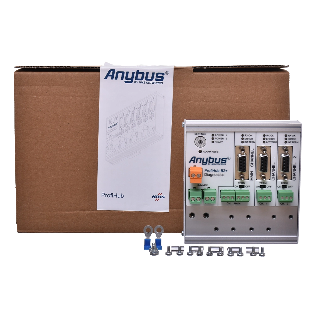
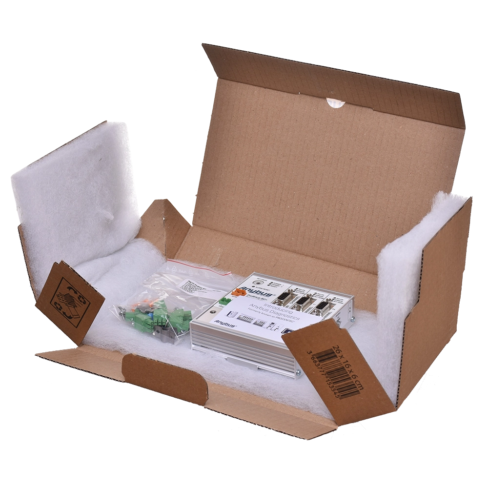
Connectors, controls and installation
Selection and commissioning
Is it necessary to change the PLC configuration?
For standard transparent repeating, there is no need for a dedicated ProfiHub address or to add it as a slave to the project. When enabling diagnostics, enter the GSD and the address of the diagnostic slave. For Robust Repeating and redundancy, check the bus timing.
Are DB9 connectors separate segments?
No. The DB9 and the terminal block for the relevant channel belong to the same segment. B2+R offers a total of three segments: MAIN, CH1 and CH2.
Does redundancy use channels 2 and 3?
In the case of B2+R, these are the outgoing channels labelled CH1 and CH2. Once redundancy is enabled, they form a single redundant pair. Do not base the numbering on another model or on a diagram of the entire family.
Is it possible to connect 31 stations to each segment, regardless of its length?
The number of devices and the cable length are two separate limits. Ensure you adhere to the length specified for the selected speed, use the correct terminations, and do not exceed the number of connected devices. To make maintenance easier to manage, we recommend dividing the network into smaller groups.
Does ProfiHub have its own web-based diagnostics?
It does not have its own Ethernet web interface. It transmits diagnostic data via PROFIBUS; for a web-based overview, the supported display in the standalone ComBricks system can be used.
Will Robust Repeating eliminate all communication errors?
No. It checks the start of the telegram and helps limit the forwarding of interference-related messages. A faulty cable, incorrect termination or incorrect bonding must be corrected. This mode also changes the delay and requires the MinTSDR setting to be checked.
Why does the alarm trigger an error when there is only one power supply?
ProfiHub monitors both power inputs. If the second input is missing, an alarm is triggered. Connecting a single power supply to both inputs will suppress this alert; independent power supplies are required for true redundancy.
Can the device be used outside the control cabinet?
The B2+R has an IP20 rating. Installation must be suitable for the environment and a temperature range of -25 to +70 °C. For a higher protection rating, select another suitable model or an appropriate protective enclosure.
Why order from FOXON
We have been an official distributor for HMS Anybus (formerly PROCENTEC) since 2007.
We will select the ProfiHub based on the specific network. We will assist with segment division, redundancy and the transmission of diagnostic data to the control system.
Proposed network layout
We will review the network speed, cable lengths, number of stations and control cabinet locations. We will propose separate segments to suit the installation.
Selecting accessories
We will select the cabling, PROFIBUS connectors and power supply. We will check the termination of the individual segments.
Redundancy verification
We will assess both ends of the connection, the cable routing and the necessary device settings.
PLC diagnostics
We can advise you on the GSD, the address and the selection of diagnostic data for the control system.
Measurement and maintenance
We can help you distinguish between a physical layer problem and a communication error, and select the appropriate diagnostic tool.
Delivery in accordance with the project
Before placing an order, we will confirm the availability of the specific model, the quantity and the delivery date.
Manual, technical data sheet and diagnostic files
The Downloads tab contains the English manual, the datasheet for 17210R, the GSD file for the diagnostic slave and declarations of conformity. Select the switch setting according to the serial number. We will confirm the dimensional drawing for the hardware revision to be supplied.
Open downloads
PROFIBUS: 3 Sins and 10 Tips
The PROFIBUS industrial bus is highly tolerant and will forgive many faults. But if a critical fault occurs—or several small ones accumulate—you will definitely notice. That’s why this aging industrial network deserves attention. Even if faults on your network are still rare, they will gradually accumulate. What do our technicians recommend? What are their 10 tips for maintaining PROFIBUS?
Highlighted items are mandatory.

Training PROFIBUS - Basics, Diagnostics & Network Troubleshooting, 2 days
1 076,90 EUR Incl. VAT
ComBricks Standard set for permanent monitoring of one PROFIBUS network / segment
3 037,10 EUR Incl. VAT
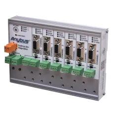
ProfiHub B5+R PROFIBUS multi-repeater
1 724,25 EUR Incl. VAT
Related products3
Training PROFIBUS - Basics, Diagnostics & Network Troubleshooting, 2 days
1 076,90 EUR Incl. VAT
ComBricks Standard set for permanent monitoring of one PROFIBUS network / segment
3 037,10 EUR Incl. VAT
ProfiHub B5+R PROFIBUS multi-repeater
1 724,25 EUR Incl. VAT